
Before your eyelet machine ships, confirm the final machine drawing and utility sheet for the exact configuration you ordered. Then verify four things at the actual installation point: the correct electrical supply, clean and stable compressed air if required, a level floor with adequate load capacity, and a clear delivery route that can handle the packed machine.
Mark the final position, prepare safe utility isolation, reserve operating and maintenance space, and record each check with a name, date and measured result. Do not approve the site from catalogue data or memory; approve it against the documents for your machine serial number and options.
The rule that prevents most installation delays: Never prepare the site from a similar model’s brochure. A feeder, double head, support table, guard, transformer or custom fixture can change the machine envelope, weight, utility load and access requirement. Use the approved general arrangement drawing, packing list and utility schedule for the machine being delivered.
Why Site Preparation Matters Before an Eyelet Machine Arrives?
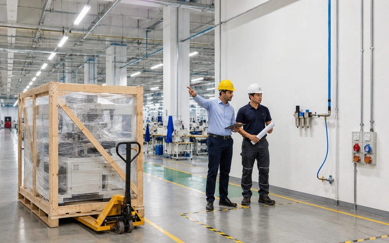
A new eyelet machine often passes its factory trial and still loses days at the customer’s plant. The cause is rarely the basic eyelet-setting process. The electrician finds the wrong voltage at the proposed position. The air line reaches the machine but cannot hold pressure while nearby equipment is running. A doorway is wide enough for the machine but not for the crate, pallet truck or turning radius. The floor looks flat until the frame is levelled. Or the machine fits the marked rectangle, but an operator cannot load a large curtain panel or open an electrical cabinet.
These are installation-intent problems. You solve them by checking the site as a working system, not as an empty patch of floor. The machine needs utilities at the correct quality, a stable base, a safe route into the building, and enough surrounding space for production, guarding, cleaning and service.
This checklist applies to bench, floor-standing, pneumatic, electric and automatic eyelet machines. Not every item applies to every model. Manual presses may need only a rigid bench and secure mounting. Pneumatic units may need compressed air but no electrical power. Automatic feeding systems can require both power and air, plus more room for bowls, tracks and controls. The final authority is always the documentation supplied for your ordered configuration.
Documents and People to Confirm First
Do not ask one person to “get the area ready” without giving that person the approved inputs. Site preparation crosses purchasing, maintenance, electrical work, compressed-air supply, production layout, safety and logistics. Assign one coordinator, then name an owner for each sign-off.
Collect the machine-specific documents
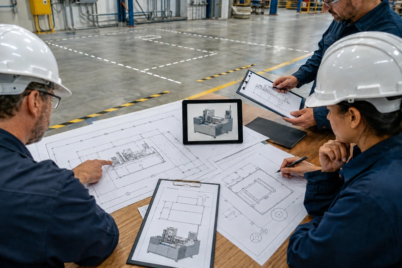
- Approved general arrangement drawing showing the machine footprint, overall envelope, operator side, service doors and utility connection points.
- Final quotation or order confirmation listing feeders, heads, guards, work supports, conveyors, transformers and custom fixtures.
- Utility schedule stating voltage, phase, frequency, connected load, protective-device guidance, grounding and compressed-air requirements where applicable.
- Machine weight, packed weight, centre-of-gravity or lifting information, and any anchoring or anti-vibration instructions.
- Packing dimensions and packing method, including separate crates or accessories.
- Installation, operation and safety manual in a language your installation team can use.
- Planned delivery date, installer date, required lifting equipment and customer-supplied tools or consumables.
Hold a short pre-installation review
Bring the project coordinator, electrician, maintenance technician, air-system owner, production supervisor, safety representative and receiving or rigging lead to the proposed location. Review the same drawing together. A ten-minute walk-through often exposes conflicts that remain invisible in an email chain: an air drop on the wrong side, a column inside the workpiece path, an overhead cable tray blocking a lift, or a fire exit that cannot be narrowed.
1. Power Checklist
Your goal is not simply to find an outlet. You need the correct and stable supply at the machine disconnect point, installed according to the manufacturer’s documentation and local electrical rules. Electrical work should be completed and verified by qualified personnel.
Match the complete electrical identity
Check voltage, number of phases and frequency as a set. A machine marked for one voltage is not automatically suitable for another, even if the plug can be changed. Confirm whether the ordered machine includes a transformer or other conversion equipment, and whether auxiliary equipment has a separate supply. Feeding bowls, dust extraction, lighting, heaters, conveyors or marking devices may add loads that are not obvious from the main motor.
- Nameplate or final utility sheet matches the site voltage, phase and frequency.
- Connected load and recommended upstream protection have been reviewed by your electrician.
- A dedicated circuit is provided when required; the circuit is not assumed available because an unused socket is nearby.
- Protective earth or grounding is installed and tested according to the machine documentation and local requirements.
- The isolator or disconnect is accessible, identifiable and not hidden behind the machine after positioning.
- Cable route is protected from wheels, sharp edges, hot surfaces, moving material and water or cleaning traffic.
- Plug, socket, cable entry and connector type are agreed before the installer arrives.
Measure at the proposed connection point
Record actual electrical measurements at the point where the machine will connect. If your plant experiences voltage fluctuation, generator operation, frequent trips or heavy load changes, tell the supplier before commissioning. A supply that appears correct with the area idle may behave differently when compressors, welders or large motors start.
Do not energize the machine merely to prove that power is present. Final connection, phase checks, rotation checks where relevant, safety-circuit verification and first energization should follow the manufacturer’s installation procedure. Lockout and isolation arrangements must be ready before work begins.
2. Compressed-Air Checklist
If your machine is pneumatic or uses air for feeding, clamping, blowing or actuation, pressure alone is not enough. You need adequate pressure and flow at the machine while production is running, with air quality that protects valves and cylinders. A gauge at the compressor room does not show what reaches a machine through a long, undersized or heavily shared line.
Confirm pressure, flow and connection
- Required operating pressure range is taken from the final machine manual or utility sheet.
- Required air consumption or flow—including simultaneous functions and optional equipment—is confirmed with the supplier.
- Pressure has been measured at the proposed machine drop under realistic plant demand, not only with other users stopped.
- Pipe and hose bore, length, fittings and quick couplers are sized to avoid excessive pressure drop.
- The connector standard and thread are agreed; suitable adapters are available without building a fragile stack of fittings.
- A local shutoff is accessible and can isolate the machine safely for service.
- Flexible hose is long enough for connection but does not cross an aisle, create a trip hazard or rub against moving parts.
Prepare air quality, not just air pressure
Water, rust, scale and excess oil can make small pneumatic components unreliable. Review the machine’s filtration, drying and lubrication instructions. Do not add an airline lubricator simply because another machine uses one; some equipment is designed for non-lubricated air. Drain low points and filters, inspect the proposed drop, and correct known contamination before connecting a new machine.
- Plant air quality is compatible with the machine supplier’s requirement.
- Filter, regulator, dryer or separator is installed where specified and accessible for inspection.
- Condensate is drained safely; the line has been cleaned or blown down using your plant’s approved procedure before machine connection.
- Leaks are repaired and the pressure remains stable through repeated cycles.
- The compressor and receiver have enough reserve capacity for the new demand and normal simultaneous users.
Common mistake: Do not set the plant regulator above the machine’s permitted pressure to compensate for an undersized line or restrictive coupler. Correct the pressure-drop cause and regulate the machine within its approved range.
3. Floor, Bench and Foundation Checklist
An eyelet machine produces a short pressing load every cycle. The floor or bench must support the static weight and keep the tooling aligned while operators load material and the machine cycles. The right preparation depends on the machine type: a small manual press needs a rigid, securely anchored bench; a compact pneumatic model may be portable; a floor-standing automatic system may need levelling, anchoring or a structural review.
Verify support and condition
- Machine operating weight, accessory weight and any local point loads are confirmed from final documents.
- A competent person has confirmed the floor or platform can support the installation, especially on mezzanines, suspended floors or areas with unknown construction.
- The surface is sound, clean, dry and free from loose tiles, cracks, pits, drains or joints that interfere with feet or anchors.
- Floor level and flatness have been checked across the full footprint, not judged by eye.
- Levelling pads, shims, anti-vibration mounts, anchors or grout are available only as specified or approved by the manufacturer.
- For a bench machine, the bench capacity, stiffness, height and mounting-hole pattern are suitable, and fasteners can be accessed from below.
- Anchoring will not strike embedded services, reinforcement or post-tensioning; drilling approval is complete where required.
Mark the working envelope, not only the footprint
Tape the machine footprint on the floor, then mark the operator position, electrical cabinet swing, guard movement, feeder access and maintenance zones. Next, bring the largest real workpiece to the location. A curtain panel, tarpaulin, bag body or sheet can need far more room than the machine itself. Move the sample through the intended loading, positioning and unloading motions.
Keep aisles, emergency routes, extinguishers and safety equipment clear. Avoid placing the machine where doors, columns, racks or passing forklifts force the operator into an awkward posture. If large flexible materials need support tables or rollers, include them in the final layout before utilities are dropped.
4. Delivery and Access Checklist
Measure the route for the packed shipment, not just the unpacked machine. Start at the truck position and follow every movement to the final foundation. The limiting point may be a gate, ramp, dock plate, elevator door, corridor corner, low beam or the last turn into the production area.
Survey the complete route
- Truck access, delivery time restrictions, unloading area and weather protection are confirmed.
- Crate dimensions and packed weight are compared with every door, gate, lift, ramp, dock and corridor on the route.
- Turning space has been checked using the crate length and handling-equipment geometry, not doorway width alone.
- Overhead clearance includes lights, sprinklers, pipes, cable trays, door closers and lifting equipment.
- Floor, ramp, dock plate and freight elevator capacities are suitable for the combined load of machine, packing and handling equipment.
- Thresholds, slopes, steps, drains and damaged floor sections have a safe handling plan.
- Temporary removals—doors, rails, racks or guards—are approved, scheduled and assigned for reinstatement.
- The route will be barricaded or controlled during movement so normal traffic cannot enter the handling zone.
Plan unloading and internal movement
Agree who supplies the forklift, crane, pallet truck, skates, slings, spreader bars and operators. Confirm the rated capacity at the required load centre and lift height. Do not use the machine frame, feeder bowl or guards as improvised lifting points. Follow the lifting labels and instructions supplied with the shipment.
Decide where the crate will be inspected and opened. Reserve a clean staging area for loose accessories, tooling and documentation. Keep the packing until the shipment has been checked, and photograph any impact, puncture, tilt indication, moisture or missing item before moving further. If the final room cannot receive the crate, agree the safe unpacking point and protected route for the unpacked machine in advance.
5. Layout, Safety and Production-Readiness Checks
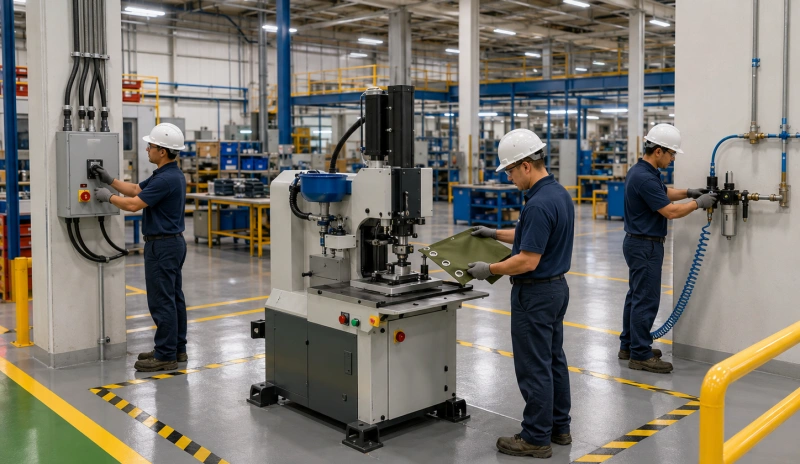
Power, air, floor and access are the four main site-preparation blocks, but the machine is not ready if the surrounding work area creates a new hazard or prevents normal production. Finish the layout with the people and materials that will use it.
- Operator has a stable standing or seated position and can see the setting point without overreaching.
- Foot pedal location, if fitted, allows a balanced posture and cannot be triggered by passing traffic or falling material.
- Guards, covers and cabinet doors can open through their full travel.
- Emergency stop, main isolator and pneumatic shutoff remain visible and reachable.
- Lighting is adequate at the die area, feeder and inspection point without glare or deep shadows.
- Material infeed, finished-part outfeed, scrap and eyelet storage have defined locations.
- Maintenance staff can reach filters, regulators, bowls, tracks, dies, lubrication points and electrical panels.
- Noise, dust, temperature, humidity, corrosive atmosphere and washdown conditions have been disclosed to the supplier where relevant.
- Required local risk assessment, permits, guarding review and operator training are scheduled before production release.
One Week Before Delivery: Run a Readiness Review
Do not wait until the truck is at the gate to discover that a utility contractor has not finished. About one week before delivery—or earlier for a complex installation—walk the route and installation area with the checklist. Record evidence rather than verbal assurances.
| Area | Evidence to record | Owner | Status |
| Documents | Drawing revision, utility sheet, packing list and manuals received | ☐ | |
| Power | Measured supply; circuit, protection, earth and isolator checked | ☐ | |
| Air | Dynamic pressure/flow and air-quality arrangement verified | ☐ | |
| Floor | Capacity, level, footprint, bench/anchors and work envelope checked | ☐ | |
| Access | Route measurements, capacities, lift plan and staging area confirmed | ☐ | |
| Safety/layout | Clearances, emergency access, ergonomics and local review complete | ☐ | |
| People | Installer, electrician, rigger, maintenance and operator dates confirmed | ☐ |
Installation-Day Handover
On delivery day, give the installer one named site contact and the latest documents. Stop if the received machine, utility label or packing information differs from what the site was prepared for. A small discrepancy can signal a configuration change that affects connection or lifting.
- Inspect the shipment before unpacking. Record crate condition, shock or tilt indicators, water damage and package count.
- Confirm the machine identity. Match model, serial number, options and utility label to the order and installation documents.
- Control the movement route. Barricade as planned and use only approved handling points and rated equipment.
- Position and level the machine. Follow the manufacturer’s sequence before anchoring or connecting utilities.
- Connect utilities under safe isolation. Qualified personnel should complete and document electrical and pneumatic work.
- Complete pre-start checks. Verify guards, emergency stops, tool installation, lubrication, air pressure and safe direction or movement checks as applicable.
- Run commissioning material. Use the approved eyelets, washers and production sample—not random spare parts—to confirm setting quality and repeatability.
- Close the handover. Record settings, training, open issues, spare parts, manuals and the person authorized to release the machine to production.
Common Site-Preparation Mistakes
Using a product-page specification as the installation drawing
Product pages help you compare machine types. They do not capture every option, connection location or shipping condition. Prepare from the documents issued for your order.
Checking static air pressure only
A regulator may show the right pressure until the machine cycles or another line opens. Verify supply under realistic demand and correct restrictions instead of raising pressure beyond the approved range.
Measuring the machine but not the crate or turn
A machine can fit through a door after unpacking while the crate cannot reach a safe unpacking point. Route width, height, slope, load capacity and turning radius all matter.
Leaving utility drops until after final positioning
Late drops often cross operator space, prevent a cabinet from opening or create trip hazards. Mark the machine orientation and connection points before installing services.
Treating the footprint as the required floor space
The footprint excludes the operator, service access, feeder refill, guard movement and workpiece handling. Test the layout with your largest real material.
Assuming the installer will supply everything
Clarify customer and supplier responsibilities in writing: unloading, internal movement, electricians, air fittings, anchors, oils, test material, eyelets, washers, tools, interpreters and training attendees.
Copy-and-Use Final Checklist
- Latest approved machine drawing and utility schedule are on hand.
- Ordered options match the footprint, weight and utility plan.
- Power supply, protection, grounding, isolator and connector are verified by a qualified person.
- Compressed-air pressure, flow, quality, shutoff and connector are verified under demand, if required.
- Floor or bench capacity, condition, level, mounting and work envelope are approved.
- Packed-machine route and handling-equipment capacities are measured and documented.
- Unloading, staging, unpacking and waste-removal areas are ready.
- Operator, material, maintenance and emergency clearances are marked and clear.
- Environmental and safety conditions have been reviewed.
- Customer and supplier responsibilities, dates and contacts are confirmed.
- Production samples, eyelets, washers and acceptance criteria are available for commissioning.
- A named person has authority to declare the site ready or stop the installation.
Conclusion
A successful eyelet machine installation starts before the crate arrives. When you verify the exact power supply, prove the compressed-air condition at the machine, prepare a stable support, measure the full delivery route and reserve real working space, installation becomes a controlled handover instead of a series of last-minute fixes.
Use this checklist as the site-readiness framework, then fill every technical blank from the approved documents for your machine. If a requirement is missing or unclear, ask the manufacturer to confirm it in writing before you install utilities or book lifting equipment. That single habit protects your schedule, your machine and the people responsible for putting it into production.
If you are preparing for a QC Machinery installation, send us your proposed layout, utility measurements, doorway and route dimensions, floor or bench details, and photos of the final location. We can compare them with the ordered configuration and flag open points before shipment.
FAQ
How much space should you leave around an eyelet machine?
There is no universal clearance. Use the final drawing to mark the machine envelope, then add the space required for the operator, the largest workpiece, feeder refill, full guard and cabinet movement, cleaning and maintenance. Keep aisles and emergency routes clear. Ask the manufacturer to approve the proposed layout if any side is constrained.
Does every eyelet machine need power and compressed air?
No. Manual machines may need neither. Some pneumatic machines need air only, while electric and automatic models may require power, air or both. Optional feeders and accessories can change the requirement, so check the final utility schedule for your ordered configuration.
What air pressure does an eyelet machine need?
Use the permitted range stated for the specific machine. Published examples vary, and pressure is only part of the requirement; available flow, hose size, restrictions, air quality and simultaneous plant demand also affect performance. Measure at the machine drop during realistic demand and never exceed the manufacturer’s maximum pressure.
Does an eyelet machine need to be anchored to the floor?
It depends on the machine and support arrangement. Some bench presses require secure bench mounting, while some floor-standing units use levelling feet, anchors or other approved supports. Follow the manufacturer’s instructions and obtain approval before drilling into an unknown, suspended or post-tensioned floor.
Who should sign off the site before delivery?
Use one project coordinator and named owners for electrical supply, compressed air, floor or structure, logistics and safety. The final readiness review should include production and maintenance because a site can be technically connectable yet impractical to operate or service.
What should you send the manufacturer for a pre-installation review?
Send a dimensioned layout, photos of the installation area and route, measured doorway and turning clearances, floor or bench details, utility measurements, connector information and any local environmental or safety constraints. Identify the machine configuration and drawing revision so the review is tied to the correct order.