
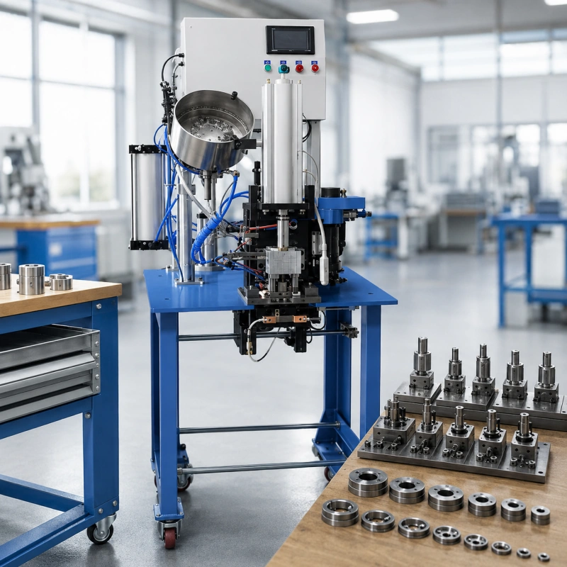
If you run several eyelet sizes, the expensive question is not which die fits one eyelet. It is where every qualified tooling set should live.
Put every size on one flexible machine and you save equipment at first. Then you pay for size changes, feeder adjustments, first-piece approval, scheduling conflicts, and a single point of failure. Dedicate a machine to every size and changeovers disappear, but capital and floor space sit idle when demand moves.
You do not need to choose one extreme. In most plants, the stronger answer is a hybrid: standardize the machine interface and the change process, package each size as a complete conversion kit, and dedicate capacity only to the families that earn it.
Quick answer: Standardize low- and medium-demand sizes on a common platform. Dedicate high-volume, high-frequency, feeder-sensitive, or quality-critical families. Keep approved crossover capacity so a dedicated line does not become a new single point of failure.
Start With the Right Meaning of Standardization
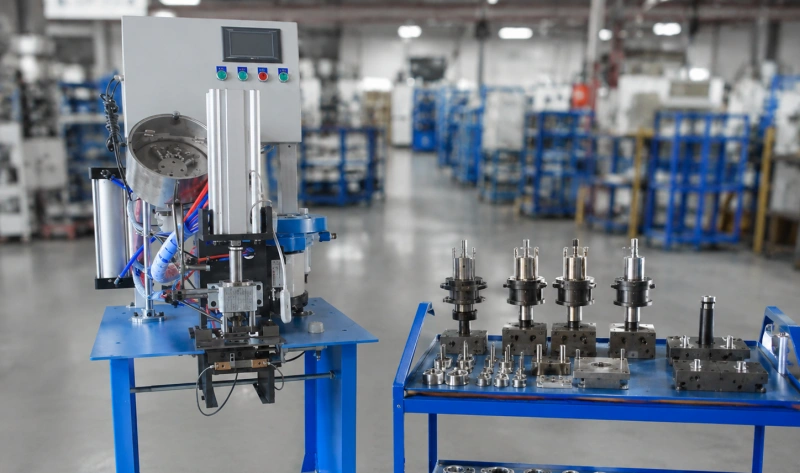
Standardization does not mean forcing different eyelets through one so-called universal die. Each qualified eyelet and material combination still needs the correct forming geometry. Your existing one-size process should already prove the eyelet, washer, material stack, punch, and die cavity.
If that match is not yet stable, solve it first with your eyelet, washer, and die-set matching process. This strategy begins after each combination can produce an approved part.
At plant level, standardization should apply to the things around the forming geometry:
- A common mounting interface or approved adapter system
- A consistent method for locating and locking upper and lower tooling
- A standard conversion cart, storage location, labels, and tooling IDs
- One setup-card format and one first-piece approval routine
- Common gauges, fasteners, torque controls, and safe change procedures where the machine design allows them
- A controlled list of machine-and-kit combinations that are actually qualified
That distinction matters. You standardize how tooling connects, moves, is identified, and is verified. You dedicate the geometry that touches and forms the actual eyelet.
Treat Each Size as a Process Package, Not a Pair of Dies
On a hand-fed press, changing size may be close to an upper-and-lower die exchange. On an automatic eyelet machine, the same decision can involve the eyelet feed, washer feed, raceway, pockets, guides, sensors, escapement, and stroke or pressure settings. If you change only the dies and leave the feeding path mismatched, the line may set a good eyelet during a hand test and still jam during production.
QC Machinery’s automatic eyelet punching machine uses customized dies and automatic feeding paths for both eyelets and washers. Its semi-automatic model automatically feeds the eyelet while the washer is placed manually. Those are different conversion scopes, even when the finished eyelet looks similar.
| Conversion-kit element | What you control |
| Forming tooling | Upper die, lower die, punch/cutter, anvils, spacers, and any dedicated holders |
| Feeding components | Bowl or hopper settings, raceways, tracks, pockets, escapements, washer shuttle, and guides as applicable |
| Machine recipe | Stroke, pressure or force setting, speed, timing, sensor position, and feeder amplitude where available |
| Placement controls | Stops, rulers, fixtures, templates, head spacing, worktable setting, or locating program |
| Quality standard | Approved sample, front and back photos, acceptance limits, gauge method, and first-piece sign-off |
| Service items | Fasteners, shims, wear parts, cleaning tools, and the minimum qualified spare set |
Give the complete package one tooling ID and one revision. If an operator can take only the dies from the rack while the feeder parts and setup card live somewhere else, you do not have a controlled conversion kit. You have a search problem waiting to stop the machine.
Build Size Families Before You Allocate Machines
Do not begin with size names such as #2, #4, 8 mm, or 12 mm. Those labels are not enough to prove compatibility across suppliers. Build families from the real process requirements.
For each active eyelet SKU, record:
- Actual eyelet and washer supplier, part number, revision, and measured critical dimensions
- Material family and thickness range already proven in trials
- Hole-making method: pre-punch, cut-and-set, self-piercing, or setting only
- Required force, stroke, throat depth, placement method, and head spacing
- Feed orientation and every size-dependent feeding component
- Average weekly demand, peak demand, lot size, and changes per week
- Changeover time from last good part to first approved good part
- Scrap and delay during startup, plus the consequence of a missed shipment
- Qualified machines, approved tooling revisions, and backup route
Two sizes belong in the same platform family only when they can use the same machine envelope and interface safely. They do not need the same forming dies. They do need compatible mounting, enough force and stroke, a workable feed path, and a repeatable qualification method.
For the geometry of an individual die, keep using your die-selection guide. Do not duplicate those dimensions inside the plant architecture matrix.
Use Four Tooling Policies, Not a Binary Choice
| Policy | Best fit | Main advantage | Main control |
| Shared standard kit | Low demand, infrequent runs, stable manual or simple feed conversion | Lowest capital and broad flexibility | Qualified machine list and controlled setup card |
| Quick-change family kit | Several sizes with recurring changes on a compatible platform | Shorter, more repeatable conversions | Complete pre-staged kit, indexed interface, first-piece approval |
| Dedicated production cell | High demand, frequent scheduling conflict, complex feeding, or costly startup | Protects capacity and process stability | Backup route and demand review so dedication stays justified |
| Dedicated spare or twin kit | Critical size where tooling failure would stop shipments | Maintenance without waiting for new tooling | Rotation, revision control, and post-service requalification |
The shared and quick-change policies standardize flexibility. The dedicated policies protect throughput or continuity. You can use all four in one plant.
Calculate the Cost of Sharing Before You Dedicate
A tooling decision should use measured lost time, not a rule such as ‘three sizes means three machines.’ Time the full event from the last good part of the old size to the first approved good part of the next size. Include cleaning, component exchange, feeder adjustment, trial cycles, inspection, and release.
Use this annual conversion burden:
Annual conversion burden = changes per year x (changeover hours + startup-loss hours) x constrained-hour value, plus annual startup scrap and changeover labor.
Then compare that burden with the annualized cost of the alternative: another conversion kit, quick-change interface, feeder module, spare tooling set, or dedicated machine. Use your real constrained-hour value. An idle hour on the bottleneck can be worth far more than an operator’s hourly wage.
Illustrative example
Suppose Size A changes onto a shared machine 12 times per week. Your measured change and approval time is 28 minutes, and startup loss adds another 7 minutes of equivalent constrained time. Across 48 working weeks, the line loses:
| Input | Illustrative value |
| Changes per year | 12 x 48 = 576 |
| Lost time per change | 35 minutes |
| Annual constrained time lost | 576 x 35 / 60 = 336 hours |
| Constrained-hour value | $85 per hour |
| Time burden | 336 x $85 = $28,560 per year |
| Startup scrap and added labor | $4,800 per year |
| Total measured burden | $33,360 per year |
If a dedicated feeder-and-tooling package costs $14,000 and removes 80% of that burden, the simple payback is about 6.3 months: $14,000 divided by $26,688 annual benefit, multiplied by 12. This is only an example. Replace every figure with your plant data and include maintenance, floor space, utilities, training, and capital cost before approval.
Also test the opposite case. If a low-volume size changes six times per year and each qualified conversion takes 20 minutes, a dedicated machine will probably sit idle. A labeled kit and disciplined changeover are usually the better investment.
When You Should Standardize?
Keep a size on a shared platform when most of the following are true:
- Demand is low or irregular, so dedicated capacity would be underused
- Runs can be scheduled in sensible campaigns without hurting delivery
- The machine envelope and mounting interface are already qualified
- Feeding components are simple to exchange or the process is hand-fed
- Changeover and first-piece approval are short, stable, and measurable
- A failed conversion does not put a high-value shipment or regulated product at risk
- Another qualified machine can absorb the work during maintenance
Standardization works best when it reduces variety outside the eyelet itself. A common holder, common fasteners, consistent storage, and one setup-card format remove decisions without pretending the forming geometry is universal.
When You Should Dedicate?
Dedicate tooling, a feeder module, a machine head, or a complete cell when one or more of these conditions is strong enough to pay for the capacity:
- A high-runner repeatedly displaces other sizes or creates a queue at the bottleneck
- Size changes happen so often that the line spends a material share of scheduled time in conversion and approval
- The feeder or raceway is sensitive and needs repeated tuning after every exchange
- The material and eyelet combination has a narrow quality window or expensive downstream failure
- A customer program requires stable traceability, locked recipes, or controlled tooling revisions
- Multi-head spacing, fixtures, or workholding make conversion slow or error-prone
- A tooling failure would stop a critical shipment and the replacement lead time is unacceptable
Dedication can stop at different levels. You might dedicate only the pre-adjusted feeder and die holder, leaving the base machine shared. You might dedicate one head on a multi-head system. Or you might dedicate the whole line. Choose the lowest level that removes the measured constraint.
When fixed spacing or simultaneous operations drive the decision, review the actual double-headed eyelet machine configuration instead of assuming a single-head conversion can reproduce the same flow.
The Hybrid Architecture Most Plants Need
A practical architecture has three layers.
Layer 1: a common machine platform
Limit the number of mounting standards and adapter types. Keep a controlled compatibility matrix that names which kits can run on which machines. Do not mark a combination as compatible because the shank fits. Run and approve the actual eyelet, washer, material, feeding path, and operating window.
Layer 2: complete family conversion kits
Group the die set, feeder parts, settings, gauges, sample, fasteners, and setup card in one location. Pre-clean and inspect the outgoing kit before it returns to storage. Pre-stage the incoming kit while the machine is still producing the current order.
Layer 3: protected high-runner capacity
Dedicate the high-runner or the conversion-sensitive family, but preserve an approved crossover route on a common platform. That crossover may run slower. Its job is resilience during maintenance, demand spikes, or tooling damage.
This design avoids both traps: one flexible machine that becomes overloaded, and a row of dedicated machines that cannot help one another.
Reduce Changeover Before You Buy More Capacity
Before you dedicate a machine, run a focused changeover study. Separate work that requires the machine to be stopped from work that can happen while it is still running. This is the core of the SMED method.
1. Film or time several real changes. Record the current sequence, delays, walking, searching, adjustment, testing, and approval.
2. Move external work out of machine downtime. Bring the clean kit, material, hardware, gauges, work order, and approved sample to the machine before the stop.
3. Replace adjustment with location. Use keyed, pinned, indexed, or otherwise repeatable interfaces where the machine manufacturer approves the design.
4. Keep settings with the kit. Record recipe values, feeder adjustments, spacer stacks, fixtures, and photos in one revision-controlled setup card.
5. Use one first-piece sequence. Check both sides of the setting, placement, retention or pull requirement, and the material around the hole.
6. Record the result. Track total change time, first-pass approval, startup scrap, and the reason for any delay.
Do not remove required safeguarding or energy-control steps to make the stopwatch look better. Your change procedure must follow the machine manufacturer’s instructions and the safety requirements that apply at your site. In the United States, OSHA treats many die-setting activities as servicing and requires hazardous-energy controls when workers are exposed.
Control the Tooling Room Like Production Equipment
A good architecture fails quickly if tooling returns to an unmarked shelf. Give each kit a visible status and owner.
| Control | Minimum rule |
| Unique ID | One ID for the complete size kit; separate serials for life-limited components if needed |
| Revision | The die, feeder parts, recipe, setup card, and approved sample carry the same current revision |
| Status | Ready, in use, awaiting inspection, repair, or quarantined; never mix these conditions |
| Location | Fixed rack position or scanned location; every component returns with the kit |
| Last-piece evidence | Keep the last accepted part or inspection record with the outgoing kit when practical |
| Maintenance trigger | Use actual condition and cycle history; do not wait for visible production failure |
| Spare policy | At least one qualified backup for regular or shipment-critical families, adjusted to lead time and risk |
Use your existing guidance on the role of die sets and eyelet machine troubleshooting for component-level training. Keep this plant-level system focused on ownership, availability, and qualified routing.
Qualify the Architecture, Not Just the First Machine
A kit that works on Machine 1 is not automatically approved for Machine 2, even if both machines accept the same holder. Frame alignment, wear, stroke reference, feeder position, and controls can change the operating window.
For every approved machine-and-kit combination, define a short qualification record:
- Machine ID, tooling-kit ID, and revision
- Eyelet, washer, and material lot used for approval
- Setup values and acceptable adjustment window
- First-piece and short-run inspection results
- Approved sample or clear front-and-back images
- Name and date of approval
- Conditions that force requalification, such as a die revision, feeder rebuild, supplier change, or machine repair
This record turns flexibility into a controlled capability. Without it, your backup route exists only on a spreadsheet.
A 30-Day Implementation Plan
1. Days 1-5: list every active eyelet SKU, complete tooling set, machine, feeder, fixture, and current storage location. Quarantine unidentified or mixed-revision components.
2. Days 6-10: measure demand, lot size, change frequency, total change time, startup scrap, downtime, and replacement lead time for each family.
3. Days 11-15: create the machine-envelope and compatibility matrix. Mark combinations as qualified, trial required, or prohibited.
4. Days 16-20: package the three most frequent conversions as complete kits. Add IDs, setup cards, approved samples, status labels, and fixed storage positions.
5. Days 21-25: run a changeover workshop on the bottleneck machine. Move preparation outside downtime and remove searching, repeated measurement, and uncontrolled adjustment.
6. Days 26-30: calculate the annual burden for each family. Approve quick-change investment, spare kits, or dedicated capacity only where the measured payback and continuity risk support it.
Review the architecture quarterly or whenever demand mix, eyelet supplier, machine fleet, or customer requirements change. A size that deserved a dedicated cell last year may return to a shared platform. A former low-runner may become the new bottleneck.
Questions to Send an Eyelet Machine Manufacturer
Before you order a multi-size system, send actual eyelets, washers, and material samples. Then ask for written answers to these questions:
- Which components change for each size: dies only, or also raceway, pockets, escapement, guides, bowl tooling, washer feed, fixtures, or sensors?
- Which mounting and locating dimensions are standard across the proposed machines?
- Can a complete feeder-and-die module be preset off-line?
- What is the demonstrated change time from last good part to first approved good part with our actual samples?
- Which size-and-material combinations have been tested on each model?
- What parts are wear items, what are their lead times, and which spares should arrive with the machine?
- What settings must be recorded, and can the control store named recipes?
- What safeguarding and energy-control procedure applies during tooling and feeder changes?
- What evidence will be delivered: sample approval, setup sheet, tooling drawings, component list, and training video?
For a fully fed application, start the technical discussion from the actual automatic eyelet punching machine scope. For lower-volume work with manual washer placement, compare the semi-automatic eyelet machine instead of paying to automate a change problem you do not have.
Final Decision: Standardize the Platform, Dedicate the Constraint
Your eyelet machine dies should not be managed as loose accessories. They are production assets tied to feeders, settings, quality standards, and delivery risk.
Standardize the platform wherever common interfaces and controlled kits give you useful flexibility. Dedicate tooling or capacity where measured demand, recurring change burden, feed sensitivity, quality risk, or replacement lead time makes sharing more expensive.
The best architecture is rarely all-shared or all-dedicated. It is a controlled hybrid: common machine platforms, complete size-change kits, protected high-runner capacity, qualified backup routes, and a tooling room that always knows what is ready to run.
If you want QC Machinery to assess a multi-size project, send your eyelet and washer samples, material stacks, size mix, weekly volume, lot sizes, and expected change frequency. With those inputs, you can compare a shared, quick-change, or dedicated layout against the work your plant will actually run.
FAQ
Can one eyelet machine use several eyelet sizes?
Yes, if the machine envelope, tooling interface, feed path, force, stroke, and safety provisions support each size. Each eyelet still needs a qualified die and process package. A holder that physically fits is not proof that the combination will feed and set correctly.
Are eyelet machine dies universal?
No. Eyelet names and die shanks are not universally standardized. Confirm the actual eyelet, washer, material, die geometry, shank or adapter, and machine model before production.
Does an automatic eyelet machine need only a die change?
Not always. Size-dependent feeder and raceway parts, pockets, guides, sensors, washer handling, fixtures, and recipes may also change. Ask the manufacturer for a component-by-component conversion list.
When should you dedicate a machine to one size?
Dedicate when the annual cost of conversions, startup loss, scheduling conflict, quality risk, or downtime exposure is higher than the annualized cost of dedicated capacity. Use measured change data and peak demand, not only average volume.
How many spare die sets should you keep?
Keep at least one qualified backup for regular or shipment-critical families, then increase coverage when replacement lead time, wear, or downtime consequence justifies it. A spare is useful only if its revision, condition, and machine compatibility are controlled.
What should be on a tooling setup card?
Include the machine ID, tooling-kit ID and revision, eyelet and washer part numbers, material range, feeder and fixture components, setup values, approved sample or photos, inspection method, safety steps, and approval record.