
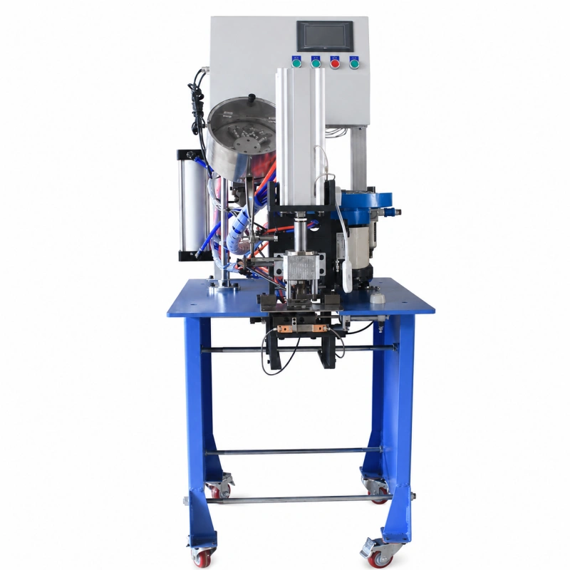
Changing the die is only half of an eyelet size changeover. If you leave the vibratory bowl feeder set for the previous eyelet, the new part may still travel around the bowl, but it may arrive doubled, tilted, backward, or too late for the machine cycle.
That is the expensive kind of setup error. The feeder appears to run, so you keep increasing vibration or moving guides. Then one adjustment creates another problem.
You need a more controlled method.
Quick answer: when you change eyelet size, you should verify the actual eyelet dimensions, install the correct change parts, reset the single-layer and guide clearances, align the discharge with the transfer track and die, tune the feeder at a normal bowl load, and approve the setup with both a feeder-only test and a production sample. Do not copy one universal gap or controller percentage from another machine.
The correct setting depends on the eyelet geometry, finish, nesting behavior, feeder tooling, controller, and required exit orientation.
This guide focuses on that changeover. If you need a general explanation of the full machine cycle, read How Automatic Eyelet Machine Works. If your existing setup has become unreliable without a size change, start with How to Improve Feeding Stability in Automatic Eyelet and Snap Button Systems.
What Changes When the Eyelet Size Changes?
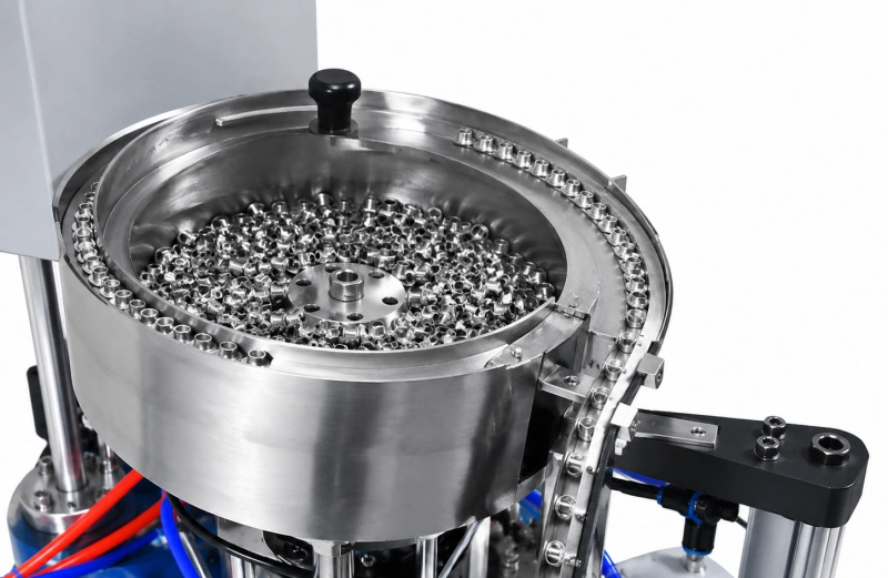
An eyelet is not defined by one number. Two eyelets sold under the same nominal size may have different flange diameters, barrel diameters, barrel lengths, flange thicknesses, weights, or surface finishes. Plating and burrs also change how the part slides.
Before you touch the feeder, record these characteristics:
- flange outside diameter;
- barrel outside diameter;
- overall height and barrel length;
- flange thickness and profile;
- weight;
- material and finish;
- roundness, burrs, and dimensional variation;
- whether loose eyelets nest inside one another;
- the orientation required at the feeder outlet.
Measure a sample from the production lot, not one perfect drawing sample. A practical starting point is 20 to 30 pieces taken from different areas of the carton. Record the minimum and maximum dimensions that matter at each restriction point.
The feeder must control three different jobs. It has to create one layer, reject the wrong orientation, and deliver one correctly oriented eyelet at a time. A setting that improves speed can make orientation worse. RNA Automation makes the same distinction in its feeder guidance: steady throughput does not automatically mean stable orientation.
Use a Clearance Window, Not a Guess
Operators often ask for “the feeder gap” as if the machine has one decisive measurement. In practice, you have several bowl-tooling clearances: the wiper or sweep gap, the guide-rail width, the top confinement, the discharge track, and the escapement or transfer pocket.
For a single-layer restriction, use a clearance window:
Maximum height of one correctly presented eyelet + running allowance ≤ gap < minimum measured height of the smallest nested or overlapping pair – rejection allowance
The running allowance must let the largest acceptable single eyelet pass without rubbing. The rejection allowance must still stop or return the smallest overlap that can occur. Because eyelets can nest, you cannot assume that two eyelets are exactly twice the height of one.
Here is the important part: if those two limits overlap, you do not have a reliable adjustment window. A wider gap will pass doubles. A tighter gap will catch good singles. You then need a different change part, a revised selector, an air reject, a second singulation feature, or a dedicated feeder. More vibration will not create missing mechanical separation.
Use the same logic for lateral guides. Start from the maximum controlling width of an acceptable part, add only enough running clearance for free movement, and confirm that the smallest bad orientation cannot pass. Your machine manufacturer may provide a changeover gauge, shim, or size-specific setting. Use that value before any general rule of thumb.
Decide Whether the Existing Bowl Can Handle the New Eyelet
Not every size change is an adjustment. Sometimes it is a tooling change.
You can usually start with the existing bowl and change parts when the new eyelet has similar proportions, the same required exit orientation, similar weight and finish, and a usable clearance window at every selector.
You should expect dedicated tooling when the flange-to-barrel ratio changes sharply, the eyelet nests more deeply, the new flange can ride under a rail, the part requires a different exit orientation, or the discharge and escapement cannot be opened or closed without losing control.
The table below gives you a practical way to think about size families. “Small,” “medium,” and “large” are relative to your approved feeder range; they are not universal eyelet numbers.
| Eyelet family | Typical feeding risk | First adjustments to inspect | Do not solve it by |
| Smaller or lighter eyelet | Bouncing, flipping, riding under a guide, two parts entering a wide track | Reduce open clearances, check top confinement, use a gentler controller setting, verify sensor detection | Increasing speed until the track stays full |
| Similar diameter, longer barrel | Nesting, hooking, standing at a selector, unstable center of gravity | Measure nested-pair height, check vertical confinement and reject tooling, confirm exit orientation | Opening every gap to stop rubbing |
| Larger or heavier eyelet | Slow climbing, congestion at transitions, pinching in guides, feeder starvation | Confirm bowl capacity and tooling range, open only the controlling guides, tune under normal load | Running maximum amplitude continuously |
| Larger flange with similar barrel | Flange overlap, shingling, contact with cover rails | Reset wiper height and side guides around the flange, check recirculation path | Adjusting the barrel track alone |
| Different finish or coating | Changed friction, sliding speed, marking, static or oil-related sticking | Clean parts and contact surfaces, compare with the approved lot, retune gently | Filing or polishing tooling during production |
If you are unsure whether the eyelet, washer, and die belong together, settle that first with How to Match Eyelet Size, Washer Size, and Die Set Correctly. Feeder setup cannot correct a wrong die or washer match.
A Repeatable Feeder Changeover Procedure
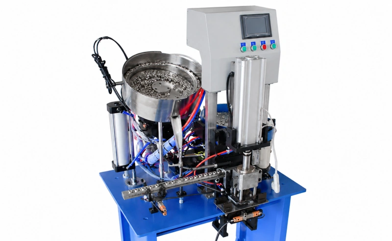
1. Stop, isolate, empty, and clean
Follow the machine manual and your plant’s lockout/tagout procedure before you reach into the bowl, track, escapement, or die area. Never defeat a guard or sensor to make adjustment easier.
Remove the previous eyelets completely. Check the bowl center, return pockets, under-track areas, discharge chute, and escapement. One old eyelet left behind can look like a random double-feed after restart.
Clean the product-contact surfaces with the method approved for your bowl lining and eyelet finish. Do not use an abrasive, solvent, or lubricant unless the manufacturer allows it. Cleaning is part of changeover because residue changes friction and effective clearance.
2. Confirm the changeover kit and baseline recipe
Match every removable rail, wiper, cover, chute, tube, escapement, pocket, and die component to the new eyelet part number. Mark change parts clearly so similar pieces cannot be mixed.
Load the approved recipe if your controller stores settings. Treat it as a starting point, not automatic approval. Hardware lots, bowl load, temperature, wear, and reinstalled tooling can shift the result.
If you have no approved recipe, record the current controller and mechanical positions before changing anything. That gives you a safe route back.
3. Install change parts without forcing alignment
Fit the size-specific parts in the sequence given in your machine manual. Seat locating faces before tightening. Tighten fasteners evenly and to the specified torque where one is provided.
Do not pull a track into alignment with its mounting bolts. Forced alignment can make the empty track look correct while creating a twist or pinch point under vibration.
With power isolated, check the whole route from the last bowl selector to the die. The discharge, inline track, escapement, and receiving pocket must share the same centerline and handoff height. A small step at the joint can catch a thin barrel edge or flange.
4. Set the single-layer and overlap guardrails
Use measured good singles and the worst realistic overlaps from your sample lot. Check every place that is intended to reject a second eyelet.
At each wiper or top restriction:
- Place the largest acceptable single eyelet in its correct running orientation.
- Close the restriction until the part is controlled, then add only the approved running allowance.
- Move the eyelet through the point by hand. It should not scrape, tilt, or spring free.
- Present the smallest nested or overlapping pair you found in sampling.
- Confirm that the pair is rejected or returned before it reaches the discharge.
At side rails or barrel guides, repeat the test with the widest good single and the narrowest bad orientation. Check at straight sections, bends, joints, and the exit. The narrowest point controls the result.
Do not use one feeler-gauge value at every station. A wiper controls layer height, a rail controls lateral position, and an escapement controls release. Each gap has a different job.
5. Check the discharge and escapement by hand
Before you restore automatic motion, hand-advance at least 20 eyelets through the final track and transfer mechanism according to the safe method in your manual.
You want to see one eyelet enter, stop, release, and seat without the next eyelet pushing it out of position. Check that:
- the flange stays flat;
- the barrel stays centered;
- the next eyelet remains behind the stop;
- the sensor sees both “part present” and “part absent” states;
- the released eyelet enters the die or transfer pocket without a step, impact, or side load.
If the transfer fails by hand, do not tune the bowl. Fix the mechanical path first.
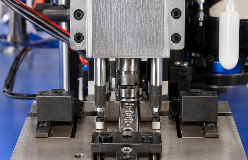
6. Restore power and establish a low, steady flow
Reinstall guards, clear tools, and restore power according to your procedure. Start below the previous production setting. Increase output in small steps until eyelets climb smoothly and remain in contact with the track.
You are not trying to make the bowl look fast. You are trying to supply the escapement with a stable queue. Too much vibration can make small eyelets bounce, overlap, or bypass reject tooling.
If your controller permits frequency adjustment or automatic tuning, follow its manual. Frequency and amplitude are not interchangeable. Frequency is tied to the feeder’s mechanical response; amplitude controls the level of vibration. Controller manufacturers such as Rodix also warn that maximum output and tuning limits protect the feeder from excessive vibration and heat.
Do not change springs, magnet gaps, weights, or base tuning as a normal eyelet changeover. Those are maintenance or engineering adjustments. If the new eyelet cannot reach the required flow within the approved control range, stop and ask the feeder manufacturer to review the mechanical setup.
7. Tune at the normal bowl load
Bowl load changes feeder behavior. Test with the quantity of eyelets you expect during production, not with five parts in an empty bowl.
Set a working minimum and maximum level. If you use a bulk hopper, adjust the level sensor and delay so the hopper adds small, controlled amounts. A large refill can bury selector tooling and temporarily change flow. A bowl that alternates between almost empty and overloaded will make a good recipe look unstable.
Run the bowl long enough to observe the level falling and being replenished. The rate should remain usable across that window. Performance Feeders recommends final tuning under a normal load and at the slowest setting that still maintains the required rate.
8. Balance feeder supply with machine demand
The bowl only needs to recover faster than the eyelet machine consumes parts. Extra speed creates pressure in the track, more recirculation, more wear, and a higher chance of overlaps.
Use a full-track sensor, demand signal, or controller delay where the system provides one. Let the feeder pause when the downstream track is full and restart before the machine is starved. Then watch the restart: a sudden surge can be as harmful as a slow feed. Use soft-start or delay settings only within the controller manufacturer’s instructions.
9. Run a feeder-only challenge test
Before pressing production material, run at least 100 eyelets through the feeding path. For a new eyelet family or a major change, use a longer sample that includes realistic lot variation.
Record:
- total eyelets presented;
- correct orientation at the escapement;
- doubles or overlaps that passed the guardrail;
- rejects and successful recirculation;
- jams by exact location;
- manual interventions;
- time to refill the downstream queue after a stop.
Do not count “parts moving around the bowl” as a pass. The useful output is one correctly oriented eyelet delivered on demand.
10. Approve first pieces, then prove a sustained run
Install the matched die and use the actual production material. Run a short first-piece sample at a controlled pace. Inspect the front, back, centering, flare, material damage, and retention requirement for your product.
Once those pieces pass, run a sustained trial. A practical factory approval might include 100 consecutive cycles with no double-feed or missed eyelet, followed by a longer production-rate run with agreed limits for jams, rejects, and manual interventions. Set the limits from your quality and output requirements; do not borrow a universal pass rate.
Count accepted settings, not empty cycles. If the feeder passes alone but fails during pressing, check the timing and transfer interface before increasing vibration.
For the fastening-quality test and record format, link this procedure to How to Document a Working Match. Your new record should add the feeder-specific values listed below.
What to Record for Each Eyelet Size?
Your setup sheet should let another trained operator repeat the changeover without rebuilding it from memory.
Record:
- eyelet supplier, part number, lot number, and drawing revision;
- measured flange diameter, barrel diameter, overall height, and nested-pair height range;
- bowl, track, and escapement change-part numbers;
- position or gauge value for every adjustable wiper, rail, cover, and stop;
- controller recipe, frequency mode, amplitude or output setting, soft-start, and delays;
- normal minimum and maximum bowl load;
- sensor positions and logic checks;
- feeder-only test quantity and results;
- production trial rate, accepted settings, misfeeds, jams, and rejects;
- approved die set, material, thickness, and quality result;
- photos of the correct eyelet orientation at critical stations.
Photograph the gauge next to the adjustment point, not just the general machine. Label the photo with the station name. That small habit saves time when two rails look almost identical.
Diagnose the First Failed Station
When the new size does not run, stop adjusting the whole feeder. Find the first station where a good eyelet changes from controlled to uncontrolled.
| Symptom during changeover | First place to inspect | Likely setup direction |
| Good singles stop at the wiper | Wiper height, burrs, part maximum height | Verify largest good part and running allowance; do not open enough to pass a nested pair |
| Doubles reach the discharge | Single-layer gap, nested-pair sample, second selector | Tighten the rejection window or add dedicated singulation tooling |
| Eyelets flip after a smooth bowl exit | Joint, top confinement, inline vibration, abrupt height change | Restore a level handoff and enough top control without pinching |
| Queue is full but the die misses parts | Escapement timing, sensor, pocket alignment | Fix release and handoff; bowl speed is not the cause |
| Queue repeatedly empties | Bowl load, approved controller range, congestion upstream | Find the first slow station before increasing amplitude |
| Flow changes after hopper refill | Level-sensor position, refill amount, overload of selector | Maintain a narrower bowl-load window |
| One lot runs and another lot jams | Dimension, burr, oil, plating, roundness, nesting variation | Compare samples and supplier tolerances before changing the machine |
This method keeps the diagnosis specific. It also protects a working station from unnecessary adjustment. For faults that are not tied to a changeover, use the broader Eyelet Machine Troubleshooting guide.
Common Changeover Mistakes
You copy the old controller setting. Similar-looking eyelets can have different weight, friction, and balance. Use the previous recipe as a baseline, then validate it.
You open every guide to stop one jam. You may remove the jam and also remove orientation control. Adjust the first failed station only.
You tune with an almost empty bowl. The setting changes as soon as production adds a normal load.
You test only perfect samples. Production lots contain dimensional spread, plating variation, and occasional burrs. Your test sample must represent the lot you will run.
You treat a double-feed as a timing problem. If two eyelets pass the mechanical guardrail, no PLC delay can reliably turn them back into one.
You change base tuning during routine setup. Spring packs, magnet gaps, and structural tuning belong to qualified maintenance or the feeder supplier, not a normal size changeover.
You approve speed before orientation. A fast bowl that sends one wrong eyelet every few minutes is not stable.
When You Should Ask for a Dedicated Feeder or Change Kit?
Stop stretching one setup across every product. Ask your eyelet machine manufacturer to review a dedicated bowl, exchangeable bowl, or engineered change kit when:
- no single-layer clearance window separates good eyelets from nested pairs;
- the required exit orientation changes;
- size changes require moving welded or non-adjustable tooling;
- the controller reaches its approved limit before you achieve stable flow;
- guide changes cause repeatability problems after every setup;
- cosmetic finishes are being scratched or marked;
- your changeover time and scrap cost are higher than the cost of dedicated tooling;
- the same high-volume eyelet returns frequently enough to justify a validated fixed setup.
Stimpson describes automatic machinery as equipment that feeds parts into position so the operator does not place them by hand. That benefit only holds when the feed system is designed for the actual fastener and the changeover preserves control from the bowl to the setting point.
Send your manufacturer real samples from every eyelet family you want to run. Include the supplier drawing, lot tolerance, finish, washer, production material, required orientation, target good-output rate, changeover frequency, and acceptable defect limit. The feeder should be proven against your parts, not selected from nominal diameter alone.
Final Changeover Checklist
Before you release the machine to production, confirm that you have:
- removed every eyelet from the previous run;
- installed and identified the correct change parts and die;
- measured the new lot rather than relying only on nominal size;
- set each gap for its actual job: layer control, lateral guidance, confinement, or release;
- challenged the overlap guardrail with nested pairs;
- aligned the bowl discharge, track, escapement, and die handoff;
- tuned the feeder at the normal bowl load and within approved controller limits;
- balanced feeder recovery with machine demand;
- passed a feeder-only orientation test;
- approved first pieces on the real material;
- completed a sustained run and recorded accepted output, jams, and interventions;
- saved the final settings, measurements, and close-up photos.
Do these steps in the same order every time. You will make fewer changes, find faults faster, and know when an eyelet is truly within the feeder’s changeover range.
FAQ
Can one vibratory bowl feeder run several eyelet sizes?
Yes, if the sizes have compatible geometry, orientation behavior, weight, finish, and a valid adjustment window at every selector and transfer point. You may need size-specific rails, wipers, chutes, escapements, or controller recipes. If a good single and a nested pair require the same clearance, use dedicated tooling rather than compromise.
What gap should you set for a new eyelet size?
There is no universal eyelet feeder gap. Measure the largest correctly presented single and the smallest realistic overlap or nested pair. Set enough clearance for the good single to pass freely while the bad condition is rejected. Follow the machine manufacturer’s gauges and limits.
Should larger eyelets always use more vibration?
No. Weight matters, but so do friction, balance, bowl load, tooling, and resonance. Increase output gradually within the approved range and judge the result at the escapement. Excessive vibration can create bouncing, overlap, wear, and misorientation.
Why does the feeder work when it is nearly empty but fail after refill?
The part load changes the feeder’s response and can bury orientation tooling. Set and test a normal minimum-to-maximum bowl level. Adjust the hopper sensor or refill amount so loading stays within that validated window.
How many eyelets should you test after a changeover?
Use a feeder-only sample large enough to expose realistic variation, then approve first pieces and a sustained production run. One common internal starting point is 100 correctly oriented feeder deliveries with no doubles, followed by a longer run against your own jam, reject, and output limits. Your quality plan and risk level should determine the final sample size.
When should you stop adjusting and call the manufacturer?
Stop when you cannot create a reliable clearance window, need to alter welded tooling or base tuning, exceed approved controller limits, see cracked springs or damaged components, or cannot keep the discharge and escapement aligned. Send the manufacturer samples, measurements, photos, video, settings, and the exact first failure point.