
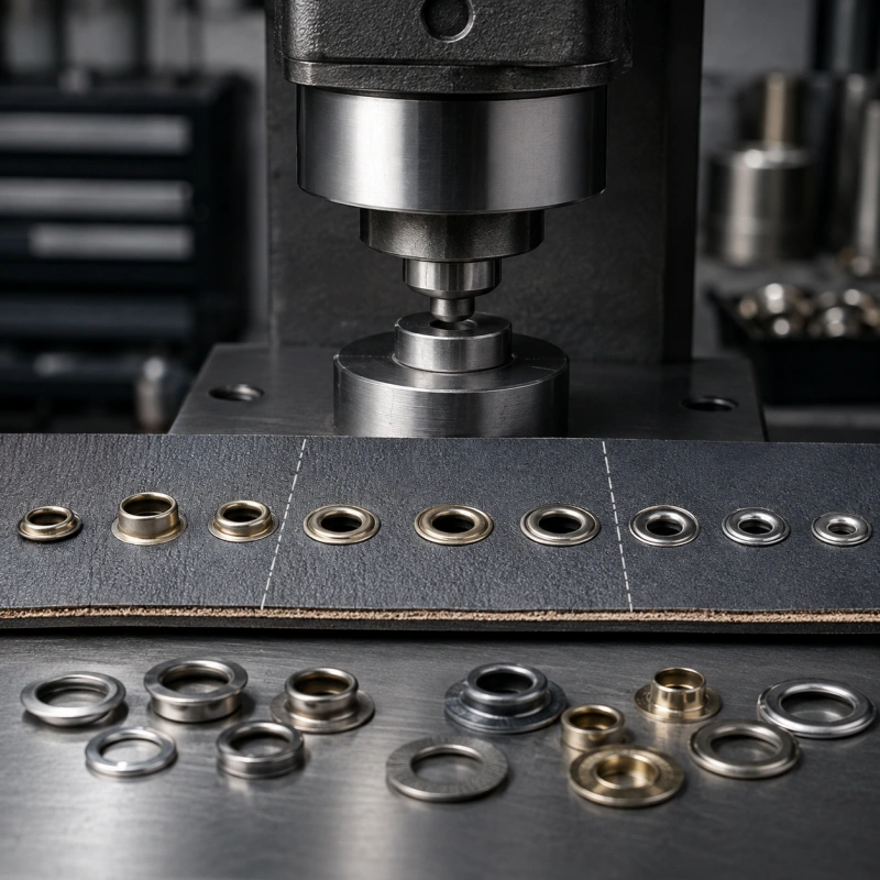
One eyelet can look acceptable at several machine settings. That does not mean all of those settings are safe for production.
At the low end, the barrel may flare just enough to look finished while the eyelet still spins or fails a pull test. At the high end, the setting may feel tight, but the flange, washer, coating, material, die, or press may already be under unnecessary stress. The correct setting sits between those two conditions.
That usable range is your eyelet setting-force window: the verified range of a machine control value within which the complete eyelet assembly meets every defined quality requirement.
You do not find this window by making one attractive sample. You establish it by holding the application constant, testing controlled setting levels, locating the lower and upper failure boundaries, and confirming a nominal setting with enough margin for normal production variation.
This guide shows you how to do that on manual, mechanical, pneumatic, hydraulic, and servo-controlled eyelet machines.
Quick Answer: How Do You Find the Correct Setting-Force Window?
Use this sequence:
- Freeze the eyelet, washer, material stack, hole, die set, machine, and inspection method.
- Define measurable pass/fail criteria before changing the setting.
- Choose the machine variable you can control and reproduce.
- Start from a safe, known setting and run a low-to-high screening trial.
- Identify the lowest level that passes every requirement.
- Continue upward until you reach the first unacceptable damage or over-setting condition.
- Confirm both sides of the proposed window with repeated samples.
- Select a nominal production setting inside the window, with margin on both sides.
- Verify the nominal setting on minimum, nominal, and maximum material stacks.
- Record the approved window, setup, samples, and revalidation triggers.
The important point is simple: a passing setting is one point; a validated window is a controlled range.
What “Setting Force” Means on Your Machine
Your machine may not display force in newtons or kilonewtons. In many factories, “setting force” is a practical name for the adjustment that changes how strongly or how far the tooling closes.
Use the value your process can reproduce:
| Machine type | Control value you may record | What else you must freeze |
| Manual lever press | stop-screw position, die gap, or closed height | handle travel, operator method, press mounting, and die position |
| Mechanical press | shut height, stroke stop, cam setting, or die gap | speed, linkage condition, ram play, and tooling alignment |
| Pneumatic press | regulated pressure, mechanical stop, stroke, and dwell | pressure while cycling, cylinder, air flow, seals, and supply stability |
| Hydraulic press | pressure setpoint, stroke/position, and dwell | oil temperature, flow, relief setting, and mechanical stop |
| Servo press | force limit, position, speed, and force-distance profile | program version, sensor calibration, tooling, and reference curve |
Do not treat a regulator reading as universal eyelet force. The same air pressure can produce a different result on machines with different cylinder areas, linkages, stops, friction, or tooling. On a mechanically stopped machine, raising pressure after the dies have reached their intended closed position may add load without improving the setting.
If you need the relationship between material thickness and press pressure, use our existing material thickness vs press pressure calibration guide. This article starts after that basic relationship and focuses on a different question: how you prove the acceptable lower and upper limits for one production setup.
Define the Application Before You Touch the Adjustment
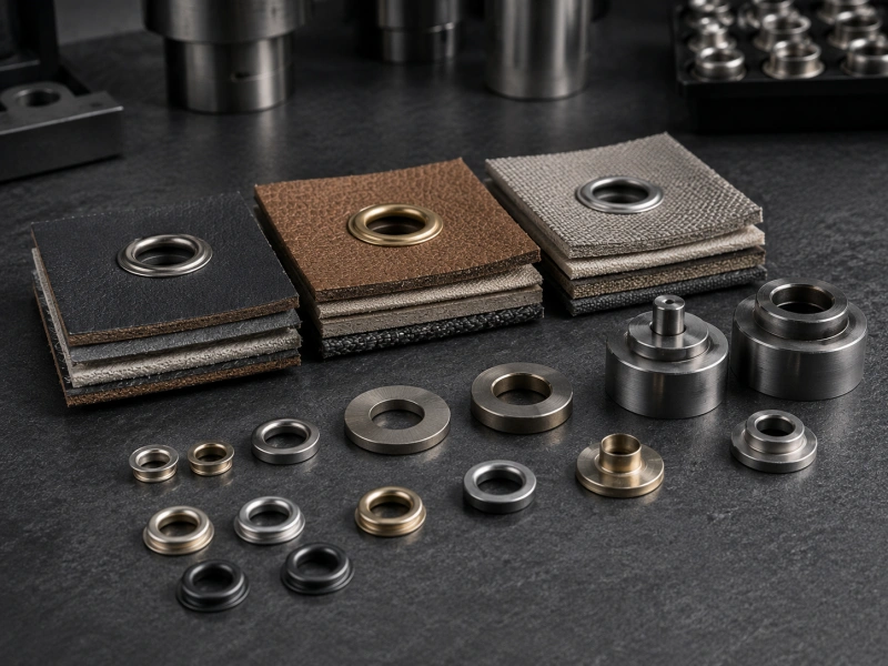
Your window belongs to a complete combination, not to the machine model by itself. Automatic machinery can feed one or two fastener components and may punch and set in one sequence, but consistent feeding does not make different eyelets, washers, or materials equivalent. The feeding arrangement, tooling, fastener combination, and material stack all form part of the validated process.
Create one trial identity and do not mix samples during the test. Record:
- machine model, serial number, head, and program or mode;
- eyelet supplier, part number, material, finish, dimensions, and lot;
- washer supplier, part number, dimensions, type, and lot;
- die-set identification, punch, cavity profile, and condition;
- hole-making method, punch size, and whether the process is pre-punched or self-piercing;
- material code, construction, number of layers, local stack thickness, and conditioning;
- setting position, edge distance, and material support;
- the control value and every related machine setting;
- inspection equipment, test direction, and acceptance criteria.
If the eyelet, washer, and dies have not already been matched, stop and correct that first. A wrong barrel length, washer hole, or die profile cannot be repaired by searching for a higher force. Use the eyelet, washer, and die matching guide before you run this validation.
Set Pass/Fail Criteria Before the Trial
If you adjust first and judge later, you will move the target whenever a result is inconvenient. Write the acceptance standard before the first sample.
Visual and dimensional checks
Every accepted setting should meet all applicable checks:
- the front flange sits flat and remains free from dents, cracks, tilt, and tool marks;
- the barrel forms an even roll, coil, or flare around its full circumference;
- the washer sits flat and cannot spin when the design requires a locked washer;
- the eyelet does not rotate or rock in the hole;
- the material shows no tearing, whitening, delamination, crushing, puckering, or unacceptable indentation;
- the finished opening and assembly height remain within the product specification;
- the hole edge and any piercing slug are controlled;
- the tooling does not bottom violently, make an abnormal sound, or leave evidence of overload.
The back side matters as much as the front. During setting, the tool turns the barrel end into a second retaining feature that grips the material or washer. A clean front face cannot prove that this hidden forming action is correct, so inspect the formed barrel from the back as part of every trial.
Retention and functional checks
Choose a test that represents how the product will be loaded. Depending on the application, that may include:
- axial pull-out;
- side or peel loading;
- spin or torque resistance;
- opening-size or plug-fit verification;
- repeated lacing, flexing, washing, vibration, or environmental conditioning;
- leakage or sealing checks;
- a customer-specific safety or attachment-strength test.
Do not borrow a universal pull-force number from an unrelated product. A paper tag, shoe upper, curtain, tarpaulin, leather bag, and child garment do not have the same risk or failure mode. Define the force, direction, loading rate, holding time, grips, sample preparation, and acceptable failure mode from the drawing, customer requirement, applicable standard, or an approved baseline.
If the material tears at a load above your requirement while the eyelet remains properly formed, that may be an acceptable material-dominated failure. If the eyelet slips out, the washer releases, or the barrel cracks below the requirement, it is not.
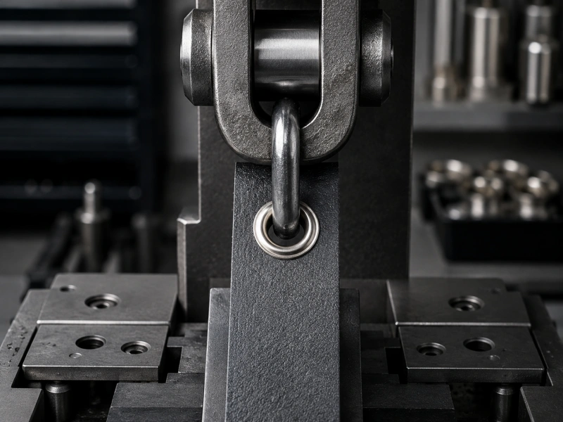
Use a Controlled Trial to Find Both Boundaries
Step 1: Prepare representative samples
Use production eyelets and washers from identified lots. Prepare the actual material stack at the eyelet location, including hems, seams, lining, tape, adhesive, reinforcement, coating, or compression. Do not validate a flat single layer if production runs through a folded edge.
Build at least three material conditions where thickness or construction varies:
- minimum expected stack;
- nominal stack;
- maximum expected stack.
If moisture, temperature, or storage changes the material, include those conditions or state the limits under which the approval is valid. Our machine-trial sample guide can help you prepare and label representative materials and hardware before a supplier or factory trial.
Step 2: Stabilize the machine
Install clean, undamaged, correctly aligned tooling. Check guards and follow the machine manufacturer’s safe setup procedure. Warm up pneumatic, hydraulic, mechanical, or servo equipment as required, then confirm utilities while the machine is cycling, not only when it is idle.
Run several setup pieces before recording results. This removes misleading readings caused by an empty feeder track, cold oil, freshly seated tooling, or the first movements after a changeover.
Never exceed the machine, cylinder, tooling, or fastener supplier’s rated limits to “find” the upper boundary. An overly tight die setting can place excess force on the press, damage tooling, and shorten machine life. Your search range must stay inside the equipment’s safe operating range.
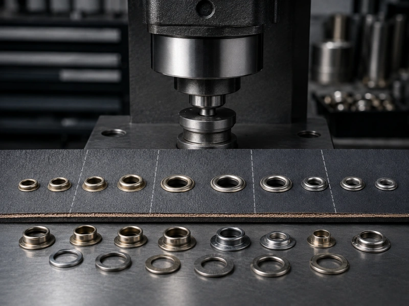
Step 3: Choose sensible setting increments
Start near a safe setting already supported by the manual, a previous setup card, or a supplier trial. If no reference exists, begin low enough to avoid crushing while still allowing controlled forming.
Use larger increments during the first screening pass and smaller increments near a pass/fail transition. The correct increment depends on the adjustment resolution and the width of the safe range. A practical starting point is 5% to 10% of the permitted adjustment span for screening, followed by finer steps around each boundary.
Do not change pressure, closed height, dwell, die position, and speed at the same time. Change one primary variable while the other inputs remain fixed. Otherwise, you will not know which change produced the result.
Step 4: Find the lower passing boundary
At each setting level, make a small consecutive group, such as five settings, and label every sample. Inspect all pieces and run the planned retention or functional test on the required specimens.
At the lower end, look for:
- incomplete or uneven flare;
- spinning eyelet or washer;
- visible gap under the flange or washer;
- assembly height above the allowed limit;
- pull-out or functional result below the requirement;
- wide variation from one sample to the next.
Increase the setting in small steps until every criterion passes. Then test one step below again. This bracketing check helps confirm that you have located a real transition rather than a lucky sample.
Call the first repeatable passing level your provisional lower qualified limit. It is not final until confirmation testing passes.
Step 5: Find the upper passing boundary
Continue upward inside the safe machine range. You are looking for the last setting that still meets every requirement before over-setting begins.
Upper-end warning signs include:
- barrel splitting, sharp petals, or excessive thinning;
- crushed or distorted washer;
- flattened, dented, or marked front flange;
- material crushing, cutting, puckering, cracking, coating damage, or delamination;
- finished opening distortion;
- tool witness marks that exceed the cosmetic limit;
- hard bottoming, abnormal vibration, noise, heat, or rapid tool wear;
- no meaningful retention improvement despite rising machine load.
When you see the first unacceptable result, step back to the previous passing level and repeat it. That previous level becomes your provisional upper qualified limit.
The upper limit is not “the most force the machine can make.” It is the highest approved process setting that still protects the product, tooling, and machine.
Step 6: Confirm the proposed window
Screening tells you where the boundaries may be. Confirmation tells you whether they are repeatable.
Run separate consecutive groups at:
- the proposed lower qualified limit;
- the proposed nominal setting;
- the proposed upper qualified limit.
As a practical factory starting point, use at least 20 consecutive settings at each point for a normal industrial application, with more samples for high-risk products, unstable materials, multiple cavities, or customer-regulated testing. Treat that number as a planning baseline, not a universal standard. Your customer specification or quality plan takes priority.
Record every defect, not just the number of good pieces. If 19 pass and one barrel cracks, the boundary has not passed merely because the average looks good.
Where possible, repeat the confirmation with a second hardware lot, another representative material lot, and after a normal restart or changeover. This exposes a narrow window that only works under perfect laboratory conditions.
Choose the Nominal Setting With Margin on Both Sides
After confirmation, you will have a qualified range:
Qualified setting-force window = lower qualified limit to upper qualified limit
Your production target should sit inside that range. Do not automatically run at the lowest passing value. That leaves no protection against a thicker material point, a harder eyelet lot, air-pressure drift, tool wear, or normal measurement error.
The arithmetic midpoint is a reasonable first candidate when risks are balanced. It is not mandatory. Move the nominal setting away from the more dangerous or more variable boundary.
For example:
- If excessive force quickly cracks a decorative flange, bias the target toward the lower half.
- If the main field risk is pull-out and the material tolerates forming well, you may bias it upward.
- If the minimum stack is vulnerable to crushing while the maximum stack tends to remain loose, one common window may be too narrow. Split the product family into two setup recipes or change the eyelet barrel length or die.
Write down both margins:
- lower margin = nominal setting minus lower qualified limit;
- upper margin = upper qualified limit minus nominal setting.
If either margin is smaller than normal process variation, you do not have a robust setup. Improve the system before production. Typical corrections include a better-matched die, a different barrel length, tighter material-thickness control, improved air supply, a sharper punch, better alignment, or separate recipes for different constructions.
Verify the Window Across Real Production Variation
A force window is only useful if it covers the approved input range. Challenge the nominal setting with the combinations most likely to fail:
| Challenge condition | Likely risk |
| Minimum material stack | crushing, marking, excessive flare, or loose clamp if the barrel is too long |
| Maximum material stack | incomplete flare, gap, spin, or pull-out |
| Hardest or thickest eyelet lot | higher forming demand or barrel cracking |
| Softest eyelet lot | over-forming or flange damage |
| Washer tolerance extremes | poor grip, tilt, or deformation |
| Lowest allowed air or utility condition | incomplete setting or slow/inconsistent stroke |
| Warm machine after a long run | drift from temperature, lubrication, or supply behavior |
| Worn-but-acceptable tooling | reduced margin and rising variation |
You do not need to test every imaginable combination. You do need to test the realistic worst cases that define your approved production range.
If your press includes force monitoring, you can record force versus distance, time, or angle and compare each cycle with a learned reference envelope. The full process signature can reveal changes that one peak-force number may miss. Use that signal as an additional process monitor, not as a substitute for direct visual, dimensional, and retention testing of the eyelet assembly.
Turn the Trial Into a Production Control Plan
Your approved setup card should contain more than one pressure number. Record:
- lower qualified limit, nominal setting, and upper qualified limit;
- machine, head, die set, punch, and program identification;
- related controls such as stroke, shut height, dwell, speed, and operating pressure;
- material construction and minimum/nominal/maximum stack;
- eyelet and washer part numbers, dimensions, suppliers, finishes, and approved lots or tolerances;
- hole method and size;
- visual, dimensional, retention, and functional criteria;
- sample quantity and inspection frequency;
- approved sample photographs or a retained golden sample;
- date, operator, inspector, and measuring-equipment identification;
- conditions that require revalidation.
At startup, run confirmation pieces after the machine stabilizes. Check the first-off samples from both sides and perform the defined retention test. During production, monitor the control value and inspect at a frequency based on risk, process history, volume, and customer requirements.
For recurring defects, use the common eyelet setting defects guide to separate force-related symptoms from hole, material, fastener, die, alignment, or wear problems. Do not widen the approved window just to keep a drifting process running.
Revalidate When the Process Changes
Repeat the window study, or run a documented partial confirmation, when any change could alter forming or retention. Common triggers include:
- a new eyelet or washer supplier;
- a change in material, hardness, wall thickness, finish, plating, or coating;
- a new material construction, layer count, thickness range, reinforcement, or adhesive;
- a different punch, die set, cavity profile, or tool repair;
- cylinder, valve, linkage, sensor, controller, or press maintenance;
- a program, speed, dwell, stroke, or closed-height change;
- relocation to another machine or head;
- repeated drift, abnormal wear, customer failure, or unexplained scrap increase.
A color or finish change can be enough to justify a check because coatings can change dimensions and forming behavior. A setup card that says only “#2 eyelet, 5 bar” cannot control those differences.
Common Mistakes When Establishing the Window
Approving one good-looking sample
One sample proves that a result is possible. It does not prove repeatability or margin.
Using pressure as the only process identity
Pressure without cylinder, stop, stroke, die, machine, and utility condition is not a transferable force specification.
Testing only the nominal material
The weakest point may be the thick seam or the thin edge, not the nominal sheet.
Raising force to solve a mismatch
More force will not correct the wrong washer, short barrel, oversized hole, off-center dies, or an unsuitable flare profile.
Using only a visual check
A hidden incomplete flare can look good from the front. Pair appearance checks with spin, dimensional, pull, or functional testing.
Setting the target directly on a boundary
A target with no margin will fail as soon as normal variation moves in the wrong direction.
Copying another machine’s number
Even similar machines can convert the same displayed pressure or stop position into different tooling loads. Transfer the validation method, not the number.
Final Decision Rule
You have established the correct eyelet setting-force window only when the same defined application passes at a confirmed lower limit, nominal setting, and upper limit; the nominal setting has usable margin; and the result remains acceptable across the approved material and hardware variation.
If the window is very narrow, do not hide that weakness with more inspection. Fix the process. Improve the eyelet, washer, hole, tooling, material control, machine condition, or recipe separation until production has room to vary without creating defects.
When you send samples to an eyelet machine manufacturer, ask for the result as a documented window rather than a single setting. Provide the complete material stack, production eyelets and washers, end-use loading requirement, appearance limits, and expected output. That gives the manufacturer enough information to build a process you can repeat after the machine reaches your factory.
FAQ
Is eyelet setting pressure the same as eyelet setting force?
Not necessarily. Pressure is often the adjustable input on a pneumatic or hydraulic machine. The force reaching the eyelet also depends on cylinder area, linkage, friction, stroke, stops, speed, tooling, and machine condition. Record the actual reproducible control values for your machine.
What is the best eyelet setting pressure?
There is no universal value. The correct setting depends on the machine, eyelet, washer, die, hole, material stack, and acceptance requirement. Establish a qualified range through controlled testing instead of copying a number from another application.
How many samples do you need to validate the setting window?
For a normal factory trial, five samples per level can be useful for screening, followed by at least 20 consecutive settings at the proposed lower limit, nominal target, and upper limit. Increase the sample size for critical products, unstable inputs, multiple heads, or customer-specific requirements.
Should you choose the lowest setting that passes?
No. The lowest passing setting defines the lower side of the window. Your production target should sit inside the confirmed range with enough margin for normal variation.
Can pull testing replace visual inspection?
No. A strong sample can still have a cracked barrel, crushed material, deformed flange, or unacceptable appearance. Use retention testing together with front, back, dimensional, and functional checks.
When should you revalidate the force window?
Revalidate after changes to the eyelet, washer, material stack, finish, hole, die, machine, program, or critical maintenance. Also revalidate when scrap, drift, wear, or field failures show that the approved setup is no longer stable.