
A finished eyelet can look acceptable from the front and still be loose, over-set, cracked, tilted, or uneven on the back. If your inspection instruction simply says “check appearance,” two inspectors may judge the same part differently. A reliable inspection standard must define what to inspect, how to inspect it, where to measure it, and what result requires rejection or process stoppage.
This guide provides a practical acceptance method for metal eyelets and grommets installed with or without washers. It covers the front flange, formed barrel, finished assembly height, tilt, gaps, rotation, rocking, and material condition. It also explains how to convert approved samples and qualification data into measurable limits for a specific application.
There is no universal finished height, flare diameter, setting force, or allowable barrel deformation that applies to every eyelet. The correct values depend on the eyelet geometry, barrel length and hardness, washer design, material stack, hole geometry, setting-die profile, and machine setup.
For that reason, dimensional values should be established and validated for the exact application before they are used as production acceptance limits. A customer drawing, regulatory requirement, approved engineering specification, or validated product standard always takes priority over general factory guidance.
Quick Answer: What Should a Set Eyelet Pass?
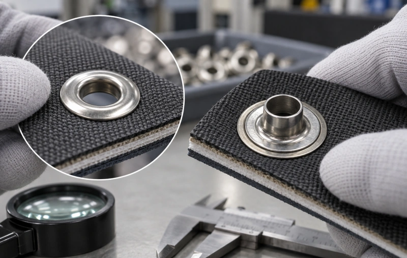
Accept a set eyelet only when all applicable requirements are satisfied. Passing one characteristic does not compensate for failure of another. For example, a correct finished height does not make an unintended barrel crack acceptable.
| Inspection item | Production acceptance requirement |
|---|---|
| Flare continuity | The formed barrel must match the approved setting profile around the required circumference. Roll-set and score-set designs must be evaluated according to their intended geometry. |
| Flare symmetry | The flare or formed-barrel envelope must remain within the product-specific dimensional and symmetry limits established during qualification. |
| Finished assembly height | Must fall within the approved lower and upper limits for the specific eyelet, washer, material stack, and setting method. |
| Tilt | The difference between the highest and lowest defined height readings must remain within the validated tilt limit. |
| Gap | No unacceptable gap may exist between the flange, washer, and material according to the approved feeler-gauge, visual, or fixture-based criterion. |
| Spin and rock | No unintended rotation or rocking is permitted under the approved inspection method. Use a validated torque method when rotational resistance is functionally important. |
| Cracks and splits | No unintended cracks or splits are permitted. Intentional score-set segmentation is acceptable only when it matches the approved setting design. |
| Sharp edges and burrs | No unintended sharp point, burr, or cutting edge that creates a safety, handling, or material-damage risk. |
| Front-face damage | Dents, coating loss, tooling marks, or deformation must remain within the approved appearance standard or signed limit sample. |
| Material damage | No unacceptable tearing, cutting, delamination, exposed reinforcement, whitening, scorching, crushing, or other damage caused by the setting operation. |
These requirements make inspection repeatable, but they do not constitute a universal international eyelet standard. Products used in medical, child-safety, fall-protection, pressure-retention, inflatable, or other regulated applications may require additional testing and stricter acceptance criteria.
If a customer or regulatory requirement is tighter than the internal standard, use the tighter requirement. Any internally developed limits should be supported by qualification records and controlled through the applicable drawing, inspection standard, or control plan.
1. Define the Inspection Condition Before You Measure
An acceptance standard applies to a defined product and setting combination. Qualification or inspection data from materially different configurations should not be pooled unless engineering has established an approved product family or common specification.
Record the following information before inspection:
- machine model, machine identification or serial number, setting head, and program or setup-card number;
- eyelet part number, supplier, lot, material, finish, and relevant barrel dimensions;
- washer part number, supplier, lot, and orientation, if a washer is used;
- die-set identification, setting profile, and tooling condition;
- material code, layer construction, and local stack thickness;
- hole diameter and hole-making method;
- production order, shift, operator, date, and inspection frequency;
- measuring-equipment identification and calibration status.
If a significant input changes, treat the next output as a new setup condition and repeat the required first-off approval.
Examples include a change in eyelet size or lot, washer type, material construction, die set, machine head, hole-making method, or machine recipe.
A setup qualified on one machine head should not automatically be transferred to another head unless equivalence has been demonstrated and documented.
2. Prepare the Part and Measuring Equipment
Measure the eyelet only after the assembly has reached the defined inspection condition.
Compressible materials such as fabric, foam, leather, coated textiles, and laminated stacks may recover after setting. If rebound affects the measurement, define a consistent delay between setting and inspection and use the same delay during qualification and routine production checks.
Use clean parts at the normal inspection condition. Remove only loose debris. Do not manually flatten or reshape the sample before measurement because doing so may hide rocking, change local stack thickness, or alter the measured assembly height.
| Check | Recommended equipment | Method control |
|---|---|---|
| Finished height and tilt | Height gauge, depth micrometer, low-force fixture, or suitable caliper where access and measuring force are controlled | Define the datum, contact points, measuring force, and reference surface. |
| Flare diameter and symmetry | Optical comparator, measuring microscope, vision system, or suitable caliper | Measure at defined angular positions. Add additional measurements when the formed geometry is irregular. |
| Gap | Approved feeler gauge, optical method, or dedicated fixture | Use consistent measuring force and do not force a gauge under the flange or washer. |
| Spin or torque | Defined hand method or calibrated low-range torque gauge | Fix the workpiece and control grip position, direction, torque, rate, and hold time. |
| Visual surface | Controlled lighting, approved sample, and magnification where required | Define lighting, viewing distance, viewing time, and magnification in the inspection standard. |
| Retention | Tensile tester or product-specific fixture | Define loading direction, test speed, peak or hold requirement, and failure criterion before testing. |
Use calibrated measuring equipment with sufficient resolution and capability for the specified tolerance. Where the tolerance is tight relative to measurement variation, verify the measurement system before using the data for acceptance decisions.
3. Inspect the Front Flange
Place the part in the defined inspection position and inspect the customer-facing side first.
The flange should sit against the material as intended by the design. Inspect the complete circumference rather than only the side nearest the operator.
Reject the part if you find an unintended crack, sharp burr, collapsed flange, bent rim, severe deformation, or tooling damage outside the approved appearance standard.
Also reject the part if the flange cuts or tears the material, traps an unintended fold, or positions the eyelet outside the location tolerance defined by the drawing.
Cosmetic judgments require controlled viewing conditions. Define the lighting, viewing distance, inspection time, and any permitted magnification in the appearance standard.
When appearance requirements are subjective, use approved reference samples or photographs that show acceptable and unacceptable boundary conditions.
Magnification may be used to confirm a suspected crack, burr, or forming defect when required by the inspection method. It should not be introduced arbitrarily if the appearance specification is based on unaided visual inspection.
4. Inspect the Formed Barrel on the Back
Turn the part over and inspect the formed barrel.
The backside geometry provides important evidence of whether the setting operation formed and retained the eyelet correctly. The acceptable appearance depends on the setting method.
A roll-set eyelet normally forms a continuous rolled or flared profile. A score-set design intentionally divides the barrel into defined segments that curl outward during setting. Do not reject intentional score-set segmentation as a crack or split when it matches the approved tooling design and reference sample.
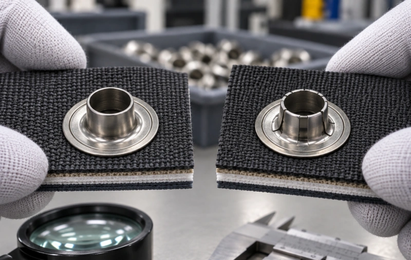
Flare or Formed-Barrel Continuity
Inspect the complete circumference or all formed segments.
For a roll-set design, the barrel should form continuously and consistently according to the approved profile. Unintended straight sections, incomplete rolling, folds, collapse, or cracking are signs of an abnormal setting condition.
For a score-set design, the number, location, shape, and spread of the segments should match the approved setting profile. The segments should form consistently without unintended tearing, excessive distortion, or hazardous sharp edges.
Any unintended crack, fracture, or sharp projection outside the intended setting geometry is a reject unless the approved product specification explicitly permits it.
Do not apply one continuity criterion to both roll-set and score-set products.
Flare Diameter and Symmetry
Measure the formed-barrel diameter or envelope using the method defined for the product.
For a generally circular roll-set profile, measurements may be taken across two perpendicular axes. Additional diagonal measurements should be taken if the shape appears irregular.
Where applicable, calculate flare spread as:
Flare spread = largest measured flare diameter − smallest measured flare diameter
Compare the result with the validated symmetry limit.
For a score-set design, a simple outside-diameter measurement may not fully describe the formed geometry. Where necessary, define segment-tip diameter, segment spread, opening diameter, angular symmetry, or another feature that represents the functional setting.
The absolute flare dimension requires its own lower and upper limits. Establish these limits using qualification samples that pass the required retention, opening-size, assembly, and visual tests.
Do not use the flange outside diameter or washer outside diameter as the flare target unless the drawing specifically defines that relationship. These are different features.
Washer Capture
When a washer is required, verify that the correct washer is present, properly oriented, and captured as intended.
The washer should not be accidentally reversed, missing, fractured, excessively cupped, folded, or trapped unevenly unless such geometry is part of the approved design.
Check washer movement according to the product requirement. If the design requires a fixed assembly, unintended washer rotation or rocking is a reject.
If controlled washer movement is intentional, document the permitted movement in the drawing or inspection specification rather than relying on inspector judgment.
5. Measure Finished Assembly Height
Finished assembly height must be defined by specific measurement datums.
Depending on the product design, the measurement may reference the front flange, formed barrel, washer, material surface, or a dedicated inspection fixture. The drawing or inspection instruction should state exactly where the measurement begins and ends.
If different inspectors select different contact points, their readings may not be comparable.
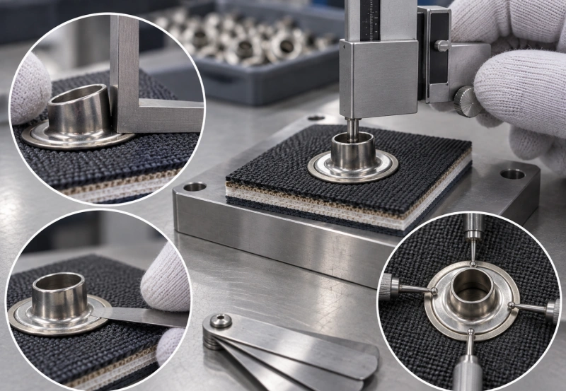
Use the following general method when four-point height measurement is appropriate:
- Place the assembly on the approved reference surface or fixture without compressing the material beyond the defined measuring force.
- Measure height at the specified angular positions, such as 0°, 90°, 180°, and 270°.
- Calculate the required result. Depending on the specification, this may include the average height, individual height readings, or both.
- Calculate tilt, where applicable, as:Tilt = highest height reading − lowest height reading
- Compare the measured values with the approved lower and upper specification limits.
Do not create a universal finished-height tolerance for all eyelets.
The acceptable range should be developed for the exact eyelet, washer, material stack, tooling, and functional requirement.
For compressible materials, confirm that the measurement method itself does not significantly compress the stack. If measurement force changes the result, specify and control that force.
If production results require an unusually wide height tolerance to remain acceptable, investigate the process rather than automatically widening the specification. Possible contributors include material-thickness variation, incorrect barrel length, tooling wear, inconsistent support, machine variation, or the need for separate setup recipes.
6. Check Tilt, Gap, Spin, and Rock
Tilt
Tilt is the difference between the highest and lowest height measurements when the approved method uses multiple measurement positions.
A part may meet an average-height requirement and still have excessive tilt. Therefore, finished height and tilt should be evaluated independently when both characteristics are important.
Excessive tilt may indicate die misalignment, uneven material support, debris, off-center feeding, material-thickness variation, or incorrect washer seating.
Use the product-specific tilt limit established in the drawing or qualification record.
Gap
Inspect for unintended gaps between the flange and material and, where applicable, between the washer and material.
If a feeler gauge is used, specify the gauge thickness, permitted insertion depth or circumferential extent, and allowable measuring force in the inspection instruction.
Do not force the gauge beneath the flange or washer because excessive force can create a gap that was not present before inspection.
A visible or measurable gap combined with unintended spinning or rocking normally indicates inadequate clamping or an incomplete setting condition and should be evaluated according to the approved acceptance criteria.
Spin and Rock
Support the material close to the eyelet without artificially stiffening or bending the assembly.
Check rotation using the approved grip and test method. Then apply alternating pressure at opposite sides if rocking is part of the inspection requirement.
For products that require a fixed eyelet, there should be no unintended movement beyond the approved limit.
A hand check may be adequate for low-risk applications when the method is clearly defined and repeatable.
For safety-related, heavily loaded, sealing, or function-critical assemblies, use a validated torque, retention, or functional test instead of relying only on subjective hand feel.
Record the fixture, direction, applied torque or force, rate, and hold time so the test can be reproduced.
7. Apply the Visual Defect Limits
| Defect | Acceptance requirement | Typical classification guidance |
|---|---|---|
| Unintended barrel or flange crack | None permitted unless the feature is an intentional part of the approved score-set design | Critical if it can cause detachment, injury, leakage, or another safety failure; otherwise typically major |
| Sharp burr, projection, or cutting edge | None permitted beyond the approved safety and appearance standard | Critical where contact or product function creates a safety hazard; otherwise typically major |
| Missing or incorrect washer | None permitted when the washer is specified | Major or critical depending on end-use risk |
| Incomplete or uneven forming | Must meet the approved roll-set or score-set geometry and dimensional requirements | Typically major |
| Loose, spinning, or rocking assembly | Must meet the approved movement or torque requirement | Major; potentially critical if detachment creates a safety hazard |
| Material tear, cut, or exposed reinforcement | None within the controlled zone unless specifically permitted | Major or critical depending on function |
| Puckering, indentation, or compression mark | Must remain within the approved visual or dimensional limit | Minor if cosmetic only; major if function is affected |
| Tool mark, dent, or coating damage | Must remain within the approved appearance and corrosion-protection requirements | Minor or major depending on visibility and functional risk |
| Blocked or distorted opening | Must pass the defined opening gauge or mating-part requirement | Typically major |
| Incorrect position or orientation | Must meet the product drawing or approved positioning tolerance | Typically major unless formally classified otherwise |
Defect classification must be based on product risk rather than the appearance of the eyelet alone.
The same physical defect may have different consequences in different products. For example, a sharp projection on a temporary display component does not necessarily carry the same risk as a sharp projection on a child-use, skin-contact, inflatable, or load-bearing product.
Define critical, major, and minor defect categories in the product quality plan, drawing, control plan, or approved inspection standard before selecting an acceptance-sampling scheme.
Do not allow individual inspectors to redefine defect severity during production.
8. Establish Product-Specific Limits From Qualification Samples
A golden sample is useful for visual comparison, but one sample cannot define the complete process window.
Develop the specification using a controlled qualification trial that represents realistic production variation.
- Freeze the eyelet, washer, material stack, hole-making method, die set, and machine setup for the trial. Clearly identify every sample.
- Evaluate the proposed operating range, including the intended nominal setting and appropriate lower and upper process conditions.
- Include relevant material-stack variation, such as minimum, nominal, and maximum thickness conditions.
- Where practical, evaluate variation across more than one representative eyelet, washer, or material lot when lot-to-lot variation may affect the result.
- Inspect the applicable characteristics, such as formed-barrel geometry, finished height, tilt, gap, spin, opening size, surface condition, and material damage.
- Perform the defined retention, torque, pull-out, sealing, mating, or other functional test required by the product.
- Identify the relationship between process settings, measured characteristics, and functional failures.
- Establish production specification limits inside the demonstrated acceptable region, allowing appropriate margin for measurement uncertainty and normal process variation.
- Do not place a production specification exactly at the first observed failure boundary.
- Confirm the selected nominal setup and specification limits through an appropriate production validation run.
- Retain approved reference samples, photographs, measurement records, and test results showing acceptable conditions and relevant reject boundaries.
The sample size used for qualification should be defined by the validation plan and the level of risk.
A small trial may be useful for engineering exploration, but it should not automatically be treated as statistical evidence of long-term process capability.
Use existing engineering or customer drawing limits when they are already available.
If limits are derived from trial data, they should be formally reviewed and approved by the responsible engineering or quality function. Inspectors should not generate new production limits from the average of each batch.
Also distinguish between specification limits and process control limits.
Specification limits determine whether the product meets requirements.
Control limits are statistical boundaries used to evaluate process behavior and detect unusual variation.
They serve different purposes and should not be used interchangeably.
9. Use a Risk-Based Inspection Frequency
Inspection frequency should reflect product risk, process capability, machine configuration, material stability, historical defect performance, and customer requirements.
The following framework can be used when developing a control plan:
| Production stage | Recommended inspection approach | Reaction |
|---|---|---|
| Setup or changeover | Perform first-off visual, dimensional, and required functional checks on consecutive parts from the new setup | Start production only after the defined first-off approval criteria are satisfied |
| Normal running | Perform periodic visual and dimensional checks at the frequency defined in the control plan | Continue production only while results remain within specification and no adverse trend is detected |
| After adjustment, jam, tooling intervention, or restart | Repeat the required first-off inspection | Identify and contain production back to the last confirmed acceptable check when product quality may have been affected |
| New eyelet, washer, or material lot | Perform the lot-change verification required by the control plan | Re-evaluate the setup if dimensions, appearance, or functional performance shift significantly |
| End of batch | Perform the required final inspection and any specified functional test | Complete the inspection record and identify the final confirmed acceptable production condition |
Do not treat these categories as a universal sampling standard. The exact sample quantity and inspection interval should be defined by the approved quality plan.
Increase inspection intensity when:
- the process is new;
- process capability has not been demonstrated;
- material variation is high;
- tooling is approaching its maintenance limit;
- a significant adjustment has been made;
- recent nonconformities have occurred;
- the product contains critical characteristics;
- the machine has multiple independently operating setting heads.
For multi-head machines, verify each setting head according to the control plan. A pooled sample may hide a defective head if head identity is not recorded.
Where acceptance sampling is used, define the sampling standard, inspection level, AQL or other acceptance criteria, and any special rule for critical defects.
10. Follow One Reaction Plan for Any Failure
- Stop the machine or affected setting head when required by the control plan. Do not continue producing uninspected material while making uncontrolled adjustments.
- Identify and segregate all potentially affected output produced since the last confirmed acceptable inspection point.
- Verify the nonconformance using the approved measurement or inspection method. Check the measuring equipment and inspect additional samples where necessary to determine the scope of the problem.
Verification of the process condition does not cancel the original failed result.
- Check the complete setup, including:
- eyelet and washer identity;
- material type and local thickness;
- hole diameter and hole condition;
- die identification and wear;
- upper- and lower-die alignment;
- machine stroke, closed height, force, pressure, or other applicable setting parameter;
- component feed orientation;
- workpiece support;
- machine condition.
- Identify and correct the cause using a controlled adjustment process. Avoid changing multiple parameters simultaneously unless the troubleshooting procedure specifically requires it.
- Run the required first-off samples again and obtain approval before restarting normal production.
- Sort, re-inspect, or retest the contained lot using the characteristic that failed and the disposition procedure defined by the quality system.
- Record the quantity inspected, quantity rejected, corrective action, verification result, and final disposition.
This inspection standard determines whether the set eyelet meets the defined requirement. It is not intended to replace a detailed troubleshooting procedure.
When you find an incomplete flare, crack, loose washer, damaged flange, tilted setting, or torn material, use QC Machinery’s common eyelet-setting defects guide to identify likely causes and corrective actions.
For process adjustment, use the eyelet setting-force window guide rather than simply increasing pressure, force, or stroke without first establishing a verified operating boundary.
11. Record the Result So Another Inspector Can Repeat It
A useful inspection record contains actual measurements and clearly defined inspection results rather than only a check mark in a pass box.
Where applicable, record:
- flare readings at each specified position;
- flare spread or symmetry result;
- individual height measurements;
- average or specified finished height;
- tilt result;
- gap result;
- spin and rock result;
- visual-defect result;
- retention, torque, or functional-test result;
- defect classification;
- final lot or part disposition.
Attach photographs when a visual acceptance boundary is difficult to describe or when the image is needed for traceability.
Protect approved reference samples from corrosion, contamination, crushing, distortion, and unauthorized replacement.
Identify each reference sample with the relevant:
- part number;
- revision;
- eyelet and washer configuration;
- material construction;
- approval date;
- approval status;
- responsible approver.
Replace or reapprove the reference sample when the product specification changes, the process changes significantly, or the physical sample no longer represents its approved condition.
Eyelet Inspection Record Template
| Field | Record |
|---|---|
| Order / product / revision | |
| Machine / head / setup card | |
| Eyelet / washer lot | |
| Material / local stack thickness | |
| Die set / hole size | |
| Setting method: roll-set / score-set | |
| Flare readings F1 / F2 / F3 / F4, where applicable | |
| Flare spread / formed-profile result | |
| Height readings H1 / H2 / H3 / H4 | |
| Finished height / tilt / result | |
| Gap / spin / rock result | |
| Visual defects and classification | |
| Retention / torque / functional test | |
| Inspector / date / disposition |
Common Inspection Mistakes
Checking Only the Front
The front flange can look acceptable while the backside contains incomplete forming, excessive deformation, unintended cracking, poor washer capture, or another setting defect.
Inspect both sides of every sampled piece when both surfaces are accessible.
For score-set products, compare the backside segments with the approved score-set geometry rather than automatically treating the segmented barrel as a defect.
Using Machine Pressure or Force as the Acceptance Criterion
Machine pressure, stroke, force, or closed-height settings are process parameters. They do not by themselves prove that the finished product is acceptable.
Accept the part based on the approved finished-product characteristics, such as dimensions, formed geometry, material condition, and required functional performance.
Process parameters should be controlled because they influence the result, but they should not replace product inspection unless the process has been specifically validated for that control strategy.
Measuring at Only One Point
A single height or diameter measurement may miss tilt, eccentricity, or uneven forming.
Use measurements at multiple defined positions when the characteristic requires evaluation around the circumference.
Changing the Limit After Seeing the Result
Establish and approve acceptance limits before production.
If evidence shows that an existing specification is unsuitable, revise it through the controlled engineering or quality process.
Do not change an inspection limit simply because a current batch falls outside it.
Treating a Golden Sample as a Complete Dimensional Specification
A golden sample is useful for showing intended appearance, forming style, and general geometry.
However, one physical sample does not define the complete acceptable process range.
Use numerical limits, functional requirements, drawings, and controlled inspection methods together with the approved sample.
Applying Roll-Set Criteria to a Score-Set Eyelet
A segmented backside is not automatically a defect.
In a score-set process, the setting tool intentionally forms the barrel into separate segments. Inspectors must know which setting method is specified and evaluate the part against the corresponding approved geometry.
Unintended tearing, irregular segment formation, unsafe sharp edges, or geometry outside the approved score-set profile can still be defects.
Confusing Specification Limits With Control Limits
A specification limit defines whether the product meets its requirement.
A statistical control limit indicates whether the process is behaving consistently.
A process can be statistically stable and still produce parts outside specification. Conversely, a process may remain inside specification while showing a statistical signal that requires investigation.
Do not use one type of limit as a substitute for the other.
Using Inspection to Compensate for a Narrow Process Window
Additional inspection may detect more failures, but it does not make an unstable setting process capable.
If results repeatedly approach the specification limits, investigate and improve the process.
Depending on the application, this may include:
- matching the eyelet barrel length more closely to the material stack;
- selecting the correct washer;
- improving hole-size control;
- correcting upper- and lower-die alignment;
- improving workpiece support;
- replacing worn tooling;
- separating setup recipes for materially different stack thicknesses;
- controlling material variation;
- optimizing the qualified machine setting.
A robust process should produce acceptable settings with reasonable margin from the failure boundaries rather than relying on inspection to separate good parts from bad parts.
Final Acceptance Rule
Accept or reject the production lot according to the approved product specification and sampling plan.
Each inspected characteristic must be evaluated against its applicable acceptance requirement, and the overall lot decision must follow the defined acceptance and rejection criteria.
A critical defect should trigger the reaction specified in the quality plan. For major and minor defects, apply the approved sampling rule rather than assuming that every sampling plan requires zero defects.
Contain or reject the affected lot when:
- a critical defect is found and the quality plan requires rejection or containment;
- a measured characteristic falls outside its specification;
- the number or type of nonconformities reaches the rejection threshold of the approved sampling plan;
- traceability is insufficient to determine which production is affected;
- the process shows evidence of an uncontrolled condition that may have produced nonconforming parts.
The practical principle is straightforward:
Inspect the formed backside as carefully as the visible front. Use more than one measurement position when necessary. Distinguish between roll-set and score-set geometry. Define acceptance criteria before production, and tie every numerical limit to the specific eyelet, washer, material, tooling, machine setup, and functional requirement.
That turns “looks good” into a repeatable quality decision that operators, inspectors, suppliers, and customers can understand and reproduce.
FAQ
What Is a Good Eyelet Flare?
A good eyelet flare is one that matches the approved setting geometry, remains within the specified dimensions, retains the assembly correctly, and does not create unintended cracks, sharp edges, or material damage.
For a roll-set eyelet, the formed barrel is generally expected to produce a controlled continuous roll or flare.
For a score-set eyelet, intentional segmented forming is part of the design and should be evaluated against the approved score-set profile.
The absolute flare dimensions must be qualified for the specific eyelet, die, material, and washer combination.
What Finished Eyelet Height Should You Use?
There is no universal finished eyelet height.
Use the product drawing or validated product specification whenever one exists.
If no specification exists, establish the target and tolerance through a controlled qualification process using the intended eyelet, washer, material stack, hole, tooling, and machine setup.
Confirm that the complete proposed height range meets the required retention, material-damage, opening, appearance, and functional requirements before releasing it as a production specification.
How Do You Measure an Uneven Eyelet?
Use multiple defined measurement positions.
For a circular roll-set profile, flare diameter may be measured across at least two perpendicular axes, with additional measurements if the shape is irregular.
Assembly height can be measured at several positions around the circumference when the measurement method supports it.
Where these calculations are specified:
Flare spread = largest flare reading − smallest flare reading
Tilt = highest height reading − lowest height reading
For score-set eyelets, use dimensions that correctly describe the segmented geometry rather than assuming that the same flare-diameter method is suitable for every design.
Can Visual Inspection Replace a Pull Test?
Not when retention strength is a functional requirement.
Visual inspection can identify conditions such as poor forming, unintended cracks, gaps, material damage, or obvious looseness.
A retention, pull-out, torque, or other functional test evaluates whether the assembly withstands its required load or use condition.
When retention is important, use the appropriate functional test in addition to visual and dimensional inspection according to the product quality plan.
When Should You Stop the Eyelet Machine?
Stop the machine or affected setting head according to the reaction plan when a result indicates that the process may be producing nonconforming product.
Typical triggers include:
- an unintended crack or fracture;
- a hazardous sharp edge;
- a missing or incorrect component;
- a loose or rocking assembly;
- a measurement outside specification;
- repeated visual defects;
- a significant adverse trend;
- a tooling or machine condition that may affect product quality.
Contain potentially affected output back to the last confirmed acceptable inspection point and repeat the required first-off approval after the cause has been corrected.
Should the Same Limits Apply to Every Eyelet Size?
No.
Acceptance limits should correspond to a defined product or an engineering-approved product family.
The relevant variables may include:
- eyelet geometry and material;
- barrel length;
- washer type;
- roll-set or score-set method;
- material type and stack thickness;
- hole size and hole-making method;
- die geometry;
- machine setup;
- functional loading;
- cosmetic requirement.
You may standardize the inspection method across similar products, but the dimensional and functional acceptance values must be qualified for the applicable product range.