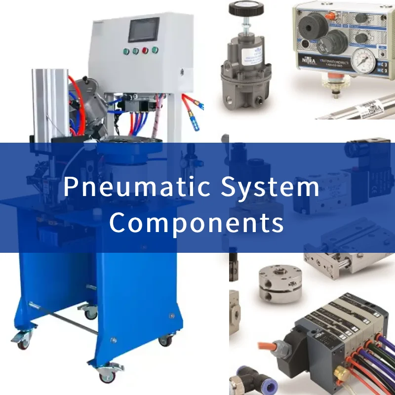
In the world of modern automation, the pneumatic system stands as a cornerstone technology—offering fast, reliable, and cost-effective motion for a wide range of industries. From car manufacturing plants to the dentist’s chair, these systems use compressed air to generate powerful movement, clamping force, rotation, and control. Whether you’re designing a new machine or maintaining existing equipment, understanding the nuances of a pneumatic system is critical to achieving long-term performance, safety, and efficiency.
What is a Pneumatic System?
Definition and Core Principle
A pneumatic system is a network of interconnected components that use compressed air to perform mechanical tasks. The key principle lies in fluid power—specifically the use of pressurized gas (typically air) to create motion or apply force.
Comparison with Hydraulic Systems
While both pneumatics and hydraulics belong to the fluid power family, they differ in medium and pressure:
| Feature | Pneumatics | Hydraulics |
|---|---|---|
| Working Medium | Compressed Air | Oil or Hydraulic Fluid |
| Operating Pressure | 60–120 PSI | 800–5000+ PSI |
| Cleanliness | Cleaner (Air-based) | Risk of fluid leaks |
| Cost | More Affordable | More Expensive |
| Application | Light to Medium Load | Heavy Load |
How Pneumatic Systems Work
The Role of Compressed Air
Air is drawn from the atmosphere, compressed using a pump or compressor, and stored in a reservoir tank. This compressed air is then filtered, regulated, and lubricated before it flows through valves and into actuators to perform work.
Types of Motion Produced: Linear and Rotary
- Linear Motion: Achieved using pneumatic cylinders (single or double acting).
- Rotary Motion: Powered by air motors or rotary actuators.
These motions enable machines to clamp, push, rotate, move, or hold components during operations.
Advantages of Pneumatic Systems
Simplicity and Affordability
Pneumatic circuits are easy to assemble with basic components. Even entry-level technicians can build and modify systems using off-the-shelf valves, tubing, and cylinders.
Reliability and Low Maintenance
Air systems suffer minimal wear and tear, especially when dry, clean air is used. Properly maintained systems often last for millions of cycles.
Fast Response Times
Because air is lightweight and moves quickly, pneumatic actuators offer rapid start-stop functionality, which is ideal for high-speed automation tasks.
Common Applications of Pneumatic Systems
- Industrial Automation: Packaging machines, pick-and-place robots, conveyors
- Healthcare: Dental drills, hospital beds, surgical tools
- DIY & Automotive: Impact wrenches, airbrushing, tire inflation
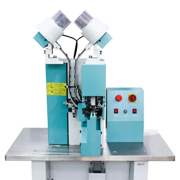
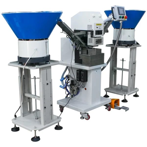
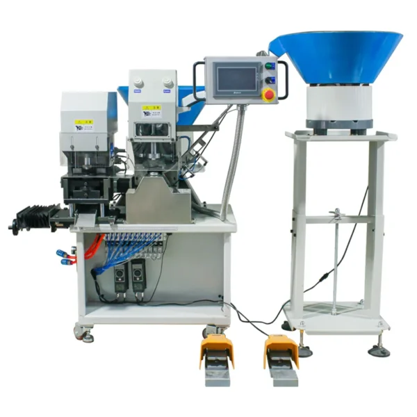
- Pneumatic Button Attaching Machine
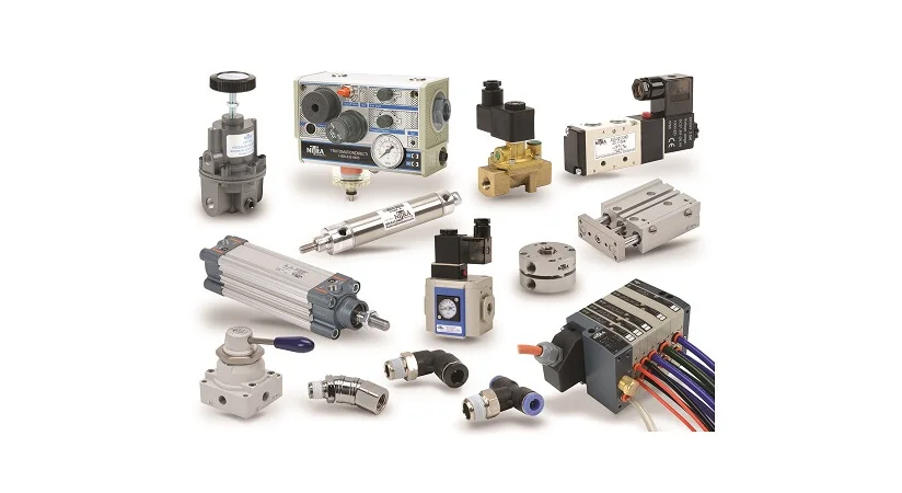
Core Components of Pneumatic Systems
Let’s break down the essential building blocks:
| Component | Function |
|---|---|
| Compressor | Generates compressed air |
| Storage Tank | Holds reserve air |
| Air Prep (FRL Unit) | Filters, regulates, lubricates air |
| Valves | Control air direction and flow |
| Actuators | Perform work—linear or rotary |
| Tubing & Fittings | Connect components |
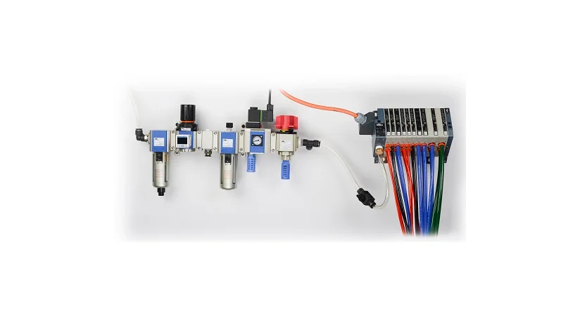
Detailed Look at Air Preparation (FRL)
Air Filtration and Moisture Removal
Particles and moisture can damage pneumatic components. A filter traps dust, oil, and water droplets, protecting actuators.
Pressure Regulation
Maintains consistent air pressure—typically 60–80 PSI for most applications.
Lubrication and Safety Features
- Lubricators inject a fine oil mist to lubricate air tools.
- Soft-start and exhaust valves protect the system during power-up and emergency stops.
Pneumatic Valves: Control and Safety
Types of Directional Valves
Directional control valves regulate the path of compressed air within the system. Common configurations include:
- 2-Way Valves – Simple on/off control for air flow.
- 3-Way Valves – Used for single-acting actuators.
- 5/2 and 5/3 Valves – Ideal for double-acting cylinders; the 5/3 version has three positions including a center off, where both ports are exhausted.
Emergency Stop Configurations
Safety is a top priority. The best practice involves using a 5-way, 3-position valve with center exhaust, which vents all air from both sides of the actuator during a stop. This reduces risk and prepares the system for a safe restart.
Valve Response and Speed Control
By adjusting the flow rate through the valve or installing external flow control valves, the speed of cylinder motion can be finely tuned for optimal performance or safety compliance.
Pneumatic Actuators Explained
Types: Single vs Double Acting Cylinders
- Single-Acting Cylinders use compressed air for extension only; a spring returns the piston to its starting position.
- Double-Acting Cylinders apply air pressure on both sides of the piston, providing control in both directions—ideal for more demanding applications.
Rotary Actuators and Grippers
- Rotary Actuators produce angular motion, useful in indexing tables and robotic joints.
- Pneumatic Grippers open and close jaws using air pressure, often used in robotic automation for handling objects.
Key Pneumatic Accessories and Add-ons
Flow Controls and Mufflers
- Flow Control Valves manage cylinder speed by controlling exhaust air.
- Mufflers reduce noise at exhaust ports, making systems quieter and safer.
Pressure Sensors and Limit Switches
Sensors provide real-time feedback for pressure conditions or actuator positions. These are vital in closed-loop control systems and help ensure machine safety and performance.
Energy Efficiency in Pneumatic Systems
Minimizing Air Leaks
Air leaks are silent energy thieves. Regular leak detection and tightening of fittings can save thousands in energy costs annually.
Using Low Pressure for Return Stroke
A return or homing stroke often doesn’t need full pressure. By designing a low-pressure return, systems can cut air consumption significantly.
Optimal Tube Sizing and Layout
Keep tubing runs short and direct. Excess tubing increases system volume, requiring more air per cycle and reducing efficiency. Where possible, mount valves close to actuators to decrease lag.
Designing a Pneumatic System: Step-by-Step
Defining Force and Motion Requirements
Begin by understanding the application:
- Load weight
- Required motion type and distance
- Cycle speed
- Environment (temperature, humidity)
Component Sizing Calculations
Use this basic formula for cylinder force:
Force = Pressure × Piston Area
From there, calculate valve size in CFM (Cubic Feet per Minute) needed based on actuator size and speed.
Building a Control Scheme
Create a pneumatic circuit diagram. Include:
- Valve types
- Actuator placement
- Sensors
- Manual or automatic controls
Simulate the design using CAD or pneumatic design software to detect flaws early.
Air Consumption Calculation Techniques
Calculating CFM Based on Cylinder Bore and Stroke
Use the following formula to estimate air usage:
Air Consumption (SCFM) = [(π × D² / 4) × Stroke × Cycles per Minute × 2] / 1728
Where:
- D is the cylinder bore in inches
- Stroke in inches
- The multiplier “2” accounts for both extend and retract motions
Using Online Sizing Tools
Manufacturers like Festo, SMC, and Parker offer online calculators. Input pressure, actuator specs, and stroke timing to get precise consumption rates and optimal sizing.
Safety Best Practices in Pneumatic Automation
Soft Start Valves
These valves slowly increase pressure when the system starts, preventing sudden actuator movements.
Exhaust Dump Valves
In emergency stop conditions, these valves instantly release stored air from the system—eliminating motion-causing energy.
Lock-out/Tag-out Methods
Always follow standard LOTO procedures during maintenance. This includes manually shutting off air supply and ensuring zero pressure before work begins.
Common Troubleshooting Tips
| Issue | Possible Cause | Solution |
|---|---|---|
| Cylinder not moving | Low pressure or blocked valve | Check supply, clean or replace valve |
| Actuator moves slowly | Leaks, long tubing | Tighten fittings, shorten lines |
| Air hissing sound | Leak | Apply soap solution to locate |
| Inconsistent motion | Dirty air or failing seal | Replace filter, inspect actuator seals |
Preventive Maintenance for Pneumatic Systems
- Weekly: Inspect hoses and fittings for damage or looseness
- Monthly: Clean filters, drain moisture traps
- Quarterly: Test valve operation, inspect cylinders for leaks
- Annually: Replace worn seals, update lubrication
Scheduled maintenance prevents breakdowns, extends component life, and maintains performance.
Innovations and Trends in Pneumatics
Smart Pneumatics and IoT Integration
New systems feature built-in sensors, wireless communication, and cloud analytics to monitor performance in real-time—driving predictive maintenance and reducing downtime.
Energy-Saving Technologies
Innovations like variable speed compressors, pulse valves, and smart actuators are making pneumatic systems greener and more cost-efficient.
Pneumatics vs. Electromechanical Systems
| Feature | Pneumatics | Electromechanical |
|---|---|---|
| Speed | Very Fast | Moderate |
| Load Handling | Medium | Medium to High |
| Cost | Lower | Higher upfront |
| Maintenance | Low | Medium |
| Energy Efficiency | Lower | Higher |
| Best Use | Repetitive, simple motion | Precision, feedback control |
Use a hybrid system where pneumatics handle fast repetitive actions, while electromechanics provide precise motion.
FAQs
How do I prevent moisture buildup in my pneumatic system?
Install quality filters and automatic moisture traps near compressors and point-of-use locations.
Can I use pneumatic systems outdoors?
Yes, but ensure components are rated for weather resistance and install water separators for humidity control.
What pressure is typically used in pneumatic systems?
Most operate between 60 and 120 PSI. Some applications use lower pressures for return strokes.
How do I know if my cylinder is oversized?
Check the actual force requirement. Oversized cylinders waste air and slow system response.
Can pneumatic systems be used for high-force applications?
Pneumatics are ideal for light to moderate force. For higher forces, consider hydraulics.
Are there safety regulations for pneumatic systems?
Yes, standards like OSHA and ISO require energy isolation, proper exhaust dumping, and labeled shutoff valves.