
A dense woven sheet gives an eyelet a broad, continuous surface to clamp. A safety net or open mesh does not. The flange may land partly on strands and partly over empty openings. When the material is pulled, those strands can rotate, bunch, slip, or carry the load into only one side of the fastener. A setting that looks flat on the bench can therefore distort when the finished product is tensioned.
That difference should guide how you choose an eyelet machine for fabric applications involving netting, knitted mesh, or other technical textiles. You are not simply selecting enough press force. You are designing a repeatable joint around an open structure, then choosing a machine, tooling, and locating method that can reproduce it without damaging the load path.
This guide shows you how to define the attachment point, prepare representative samples, compare machine formats, and approve the process.
It covers safety nets, debris and containment nets, sports and barrier mesh, agricultural or shade mesh, ventilation panels, filter and spacer textiles, and similar open constructions. The same machine may serve several of these products, but compatibility must be proven for each material stack and eyelet system.
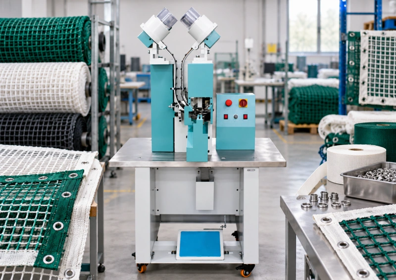
Start With the Function of the Eyeleted Point
Before you compare equipment, mark every eyeleted location on the finished product drawing and state what it does. An eyelet may retain a lacing cord, connect a panel to a frame, identify an inspection point, guide a cable, or provide a temporary handling point. Those functions do not create the same load, direction, or consequence of failure.
If you manufacture a net intended to protect people from a fall, do not treat the eyelet joint as an isolated hardware choice. The complete net system, its border construction, connectors, installation method, and required tests must satisfy the applicable product specification and local regulations. A machine sample can prove that the press forms the fastener consistently; it cannot certify the finished safety-net system.
Ask these questions before you request a quotation:
- Is the point load-bearing, positioning-only, decorative, removable, or part of a primary safety function?
- Which direction or range of directions will the cord, hook, or frame pull on the eyelet in service?
- Will the net remain tensioned, cycle between slack and tension, flap outdoors, or be folded repeatedly?
- What environment reaches the hardware: water, salt, cleaning chemicals, ultraviolet exposure, heat, abrasive dust, or wash cycles?
- Which drawing, customer specification, test method, or regulation defines acceptance for the finished product?
This first step prevents a common mistake: selecting a larger eyelet or a more powerful press and assuming it will make the finished attachment stronger. The surrounding textile, reinforcement shape, edge distance, and load direction usually determine where failure starts.
Why Open-Structure Materials Behave Differently?
| Material behavior | What happens at the die station | What you need to control |
| Large or irregular openings | The flange can bridge space and clamp an uneven number of strands | Eyelet location relative to the mesh repeat and a reinforcement that creates a continuous seat |
| Knitted or knotless netting | Loops can stretch, rotate, or run when cut | Cutting support, local stabilization and inspection for pulled or damaged loops |
| Knotted netting | A knot or crossing can sit under one side of the flange | A locating rule that avoids prohibited crossings or a joint design that accommodates them |
| Stiff coated mesh | The coating may whiten, crack, or delaminate while the strands resist forming | Sharp cutting tools, controlled support and approved visual limits |
| Soft filter or spacer textile | The stack can compress far more than its free thickness suggests | Barrel length and setting travel proven across compression recovery |
| Reinforced edge or webbing tape | The eyelet sees a layered stack instead of the base mesh alone | Samples made from the finished seam, fold, weld, or sewn reinforcement |
You should also distinguish mesh count from joint geometry. Two materials with similar opening size can behave differently because one is woven, one is knitted, and one is welded or extruded. Yarn material, strand diameter, coating, heat setting, knot design, and edge construction all change how the load reaches the eyelet.
Design a Stable Landing Area for the Eyelet
An eyelet works best when both its flange and washer clamp a stable, reasonably continuous stack. If the product drawing places the eyelet directly through open netting, inspect how much material actually sits under the circumference. The answer may change as the eyelet moves by only half a mesh opening.
In many products, you can create a better landing area with a folded border, woven tape, webbing, coated patch, welded strip, or sewn reinforcement. The reinforcement should be part of the product design, not a last-minute patch added because the press sample tears. Its width, material, attachment method, and orientation need their own drawing requirements.
Check the complete load path. A wide patch does little if it is joined to the net by a narrow seam that peels under load. A strong webbing border can still fail if the eyelet sits too close to its cut edge. If the eyelet is near a corner, reproduce the actual fold and the diagonal pull during testing.
When direct setting into mesh is required, define an allowable relationship between the eyelet center and the mesh repeat. A camera, projected target, or shaped fixture may be needed when the operator cannot locate the center reliably from an irregular edge. Do not rely on a pen mark that disappears among dark strands or moves when the mesh relaxes.
Specify the Material Stack Before the Machine
Send the machine supplier material in the same form that reaches production. A flat coupon cut from the middle of a net roll does not represent an eyelet installed through a bound edge, welded patch, or folded corner. Your sample set should include the thinnest normal location, the thickest seam crossing, the loosest mesh, the stiffest coated lot, and any left-to-right construction differences.
Record more than free thickness. For compressible technical textiles, note thickness under a defined measuring force if your specification uses one. Record opening size, strand or yarn construction, coating, reinforcement layers, seam type, and the direction of the mesh. Label machine-direction and cross-direction samples when their stretch differs.
Moisture and temperature can change the way some polymer textiles handle or recover. If your production material arrives cold, damp, or tightly rolled, include those realistic conditions in the trial or condition the material according to your documented process before setting. The process should be approved for the material state you will actually control.
Match the Eyelet, Washer and Dies to the Joint
Do not buy the machine first and choose the hardware later. Start with the opening required by the cord, hook, or connector, then define the eyelet barrel diameter, flange diameter, barrel length, base material, finish, and washer profile. Supplier trade numbers are not enough for tooling approval.
The barrel must pass through the complete reinforced stack and leave enough material for the intended flare. A barrel that is too short cannot be corrected by adding pressure. A barrel that is too long can buckle, split, or leave a loose assembly on a thin section. The washer and lower die must support the same fastener system.
Use QC Machinery’s eyelet washer and die matching guide to document the actual component dimensions before the trial. For mesh applications, add the reinforcement construction and the eyelet position relative to the strand pattern to that setup record.
A larger flange can spread clamp pressure over a wider area, but it is not automatically better. It may cover more unsupported openings, trap a raised knot, or create a stiff transition that concentrates bending at the flange edge. Approve the joint with the actual geometry and service-oriented test, not by appearance alone.
Choose the Hole-Making Method Carefully
You may pre-punch the hole in one operation and set the eyelet in another, or use a validated pierce-and-set process. The correct choice depends on the hardware, tooling, and textile construction. Press force alone does not make an ordinary eyelet self-piercing.
Pre-punching lets you inspect the cut and remove the slug before setting. It can be useful for reinforced borders, stiff coated mesh, and constructions in which trapped fibers would interfere with the flare. It also creates a transfer step: the prepared hole must remain aligned with the eyelet and must not stretch while the panel moves to the setting station.
A combined process removes that transfer, but the cutting edge must sever the local strands cleanly and manage slugs or loose fibers. On open mesh, a partial cut can pull a loop into the die instead of cutting it. That damage may extend beyond the flange where it remains visible after setting.
Use the pre-punching decision chart as a process screen, then prove the selected method on your most difficult mesh and reinforcement stack. Inspect the bare hole as well as the finished joint.
Choose the Right Level of Automation
Automatic machinery can feed one or both hardware components into position, reducing manual part placement and supporting repeatable production. That advantage matters only after you can present the textile to the dies consistently. A feeder does not correct a mesh panel that stretches, rotates, or sags during location.
| Machine format | Where it can fit | Main question for mesh production |
| Manual or bench press | Development, repair, and very low volume | Can the operator form the joint without fatigue or variable leverage? |
| Powered press with hand-fed parts | Mixed products, frequent changes and moderate volume | Can the loading method keep hands out of the closing tools while the mesh is supported? |
| Semi-automatic feed | Repeated work where one handling step is the bottleneck | Which component is fed, and how are misfeeds detected and cleared? |
| Automatic eyelet and washer feed | Long runs with stable hardware and repeatable presentation | Will actual hardware lots feed reliably, and can the operator locate flexible material at the required rate? |
| Indexed or custom cell | High-volume repeat patterns with controlled incoming blanks | Can the fixture control stretch, mesh orientation, and pitch without building stress into the panel? |
Compare output as conforming finished pieces per shift, not no-load machine cycles per minute. Include time to unfold, orient, tension lightly, locate, cycle, inspect, reposition, and stack the product. For large nets, material handling can set the pace even when fastener feeding is fully automatic.
If your product mix is still changing, compare the basic formats in the manual, semi-automatic and automatic eyelet machine guide before you specify a dedicated feeder or indexed station.
Control the Mesh Without Preloading It
The operator needs a locally flat setting area, but excessive tension can be just as harmful as slack. If you stretch the mesh to find the mark and then clamp the eyelet, the material may contract around the joint after release. That can create puckering, an oval opening, or residual load around the flange.
Use broad, low-friction support at the same working height as the lower die. Add a light frame, template, or vacuum support only if trials show that it holds the panel repeatably without changing the approved material state. For a bound edge, an edge guide may locate the centerline. For an eyelet indexed to the mesh repeat, a vision target or nest may be more reliable than an edge stop.
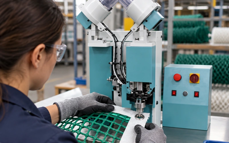
Large nets should not hang from the current eyelet position. The unsupported mass can pull the mark off-center and tilt the washer. Plan infeed and outfeed tables, bins, or rolling supports so the operator can move the product without dragging it across the floor or feeder guard.
Throat depth is based on the deepest eyelet center that must reach the tooling from an accessible edge, plus clearance for the guide, reinforcement, and normal handling. It is not determined by total net width alone. Confirm reach using the assembled product and trial the farthest location, where frame clearance and material bulk are most demanding.
QC Machinery’s throat depth guide explains how to measure that reach before you freeze the machine frame.
Run a Production-Representative Sample Trial
A no-load cycle video and a neat sample on generic fabric do not qualify the process. Send enough labeled material to reproduce the real variations and enough hardware for a continuous run. Include more than one normal incoming lot when dimensional or finish variation could affect the feeder.
Your trial plan should include these steps:
- Run the approved thin, nominal, and thick material stacks with the intended reinforcement and seam construction.
- Set eyelets at the normal edge position, near a permitted mesh crossing, and at the most difficult corner or seam location.
- Inspect the cut before it is hidden. Look for uncut filaments, pulled loops, cracked coating, delamination, displaced knots, and damage extending beyond the flange.
- Inspect the formed joint from the front, back, and side. Check flange seating, flare symmetry, washer engagement, rocking, spin, sharp edges, and trapped strands.
- Measure location, edge distance, and pitch on the relaxed finished piece using the drawing datum, not the temporary stretched position at the machine.
- Run the customer-defined pull, cyclic, environmental, or finished-product tests in the required direction and fixture. Record the failure mode as well as the peak result.
- Repeat visual and dimensional checks at the beginning, middle, and end of a continuous batch to expose feed drift, debris buildup, and tool wear.
Use the eyelet machine trial sample guide to organize the drawings, components, and production data sent with the material.
Set Acceptance Rules That Separate Appearance From Function
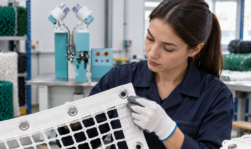
A clean-looking flare is necessary, but it is not the whole acceptance decision. Build a control plan with four layers: fastener formation, textile condition, location and pattern, and functional performance. Define each limit numerically or with approved boundary samples where possible.
| Control layer | Examples to record | Why it matters |
| Fastener formation | Finished height, flare diameter, washer engagement, spin or rock, cracks and sharp edges | Shows whether the eyelet, washer, tooling and setting travel are working as a system |
| Textile condition | Broken strands, displaced loops, coating cracks, puckering, reinforcement separation and hole position | Finds damage that the flange may partly hide |
| Location and pattern | Centerline, edge distance, pitch, and orientation relative to mesh repeat | Prevents uneven loading and installation mismatch |
| Functional result | Customer-specified pull direction, cyclic loading, environmental exposure, or assembly test | Confirms the joint in the product context rather than on appearance alone |
Keep an approved first article at the machine with the material code, reinforcement revision, eyelet and washer lots, die identification, and validated setting. If one product contains several stacks, use separate setup rows or part identifiers. “Same net, same setting” is not adequate when a corner carries twice the layers of a straight edge.
For safety-related products, retain the traceability and test evidence required by your customer and quality system. Do not substitute an informal hand pull for a specified test, and do not advertise a machine as making a compliant safety net unless the complete manufactured product has been evaluated under the applicable requirements.
Read Common Defects as Process Signals
When a defect appears, stop and separate material, hardware, tooling, and handling causes. Increasing pressure until the joint looks flat can hide the real problem and damage the mesh.
| Symptom | Likely checks | Do not assume |
| Mesh puckers after release | Material was preloaded, flange trapped uneven strands, stack was not flat | More setting force will flatten it safely |
| Loop or strand pulls into the hole | Cutting edge is dull, hole method is unsuitable, mesh lacked local support | The flange will stop the damage from spreading |
| Eyelet spins or rocks | Barrel length, washer match, flare formation, thin local stack, space under flange | Every loose joint needs higher pressure |
| Flare is higher on one side | Washer tilted, knot or seam sat under the flange, dies are misaligned | The fastener is acceptable because one side is tight |
| Coating cracks or whitens | Cut stretched the coating, forming was excessive, material was cold or unsupported | The mark is only cosmetic |
| Pitch changes across the row | Panel stretched during indexing, datum moved, unsupported weight pulled the net | The guide is correct because its mechanical pitch is fixed |
For a wider troubleshooting reference, use QC Machinery’s common eyelet setting defects guide and add mesh-specific checks for strand capture, local distortion and reinforcement separation.
Control Debris, Tool Wear and Changeovers
Mesh and technical textiles can leave short fibers, coating chips, loose filaments and small slugs around the punch, die and sensors. Establish the cleaning interval during the continuous trial. If cut quality changes before the planned interval, shorten it and record the trigger by material and cycle count.
Inspect the cutting edge, die alignment, component holders, and feeder track at startup and after a changeover. A worn punch may still penetrate an open mesh while pulling strands instead of making a clean boundary. That gradual failure can be missed if you inspect only the finished flange.
Your setup card should identify the exact dies, approved hardware, material construction, locating fixture, pressure or stroke setting, cleaning interval, and first-piece checks. After a supplier, coating, yarn, reinforcement, or fastener change, repeat the defined verification. Similar appearance does not prove process equivalence.
Include Safeguarding in the Process Specification
The closing tools create a point-of-operation hazard. Automatic component feeding reduces hand placement of eyelets and washers, but it does not remove the need for guarding and a risk assessment. The material fixture, controls, and normal loading method must work together so the operator is not encouraged to hold a loose washer inside the dies.
- Review fixed or interlocked guards, two-hand controls, presence sensing, and safe-distance requirements with your safety team.
- Provide an isolated procedure for die changes, cleaning, jam clearing, and maintenance.
- Test the response to a misfeed and make sure the operator can recover without bypassing the safeguard.
- Position supports and controls so the operator does not reach across a large net into the hazard area.
- Train to the final validated work method, including what requires an immediate stop and quarantine.
What to Include in Your RFQ
A useful request for quotation allows the manufacturer to evaluate the joint and material flow instead of quoting a generic eyelet machine for fabric. Include:
- Finished product drawings showing eyelet centers, pitch, datums, accessible edges, reinforcement, and permitted relation to the mesh pattern.
- Representative material for every approved stack, with machine and cross direction identified where relevant.
- Eyelet and washer samples, dimensioned drawings, material and finish requirements, normal lot variation and annual usage.
- The selected hole-making method, required cut condition and plan for slug or fiber removal.
- Product dimensions, weight, roll memory, handling method and the deepest required reach from an accessible edge.
- Pieces per shift, eyelets per piece, batch sizes, product mix, changeover frequency and inspection time.
- The customer-defined visual, dimensional, pull, cyclic, environmental, and finished-assembly acceptance criteria.
- Required safeguards, utilities, documentation, spare tooling, training and sample-report format.
Ask the supplier to identify the machine configuration, feed method, die set, locating method, material support, and assumptions behind the quoted output. If the application needs an indexed fixture or custom handling, require an approval drawing and a trial with your largest or most flexible product.
FAQ
Can You Set an Eyelet Directly Into Open Mesh?
Sometimes, but only after you validate the exact mesh, fastener position, eyelet, washer, dies, and service load. Many open constructions need a bound edge, webbing, or local patch to create a stable clamping area. Direct setting should be a proven product design decision, not a shortcut taken at the press.
Is an Automatic Eyelet Machine Always Faster for Netting?
No. Automatic feeding can reduce component handling, but net orientation, location, and support may remain the longest parts of the cycle. Compare conforming finished products per shift and include all handling, inspection, and changeover time.
Should You Stretch the Mesh While Setting the Eyelet?
Hold the local area flat and repeatable without adding uncontrolled tension. Setting while the mesh is stretched can produce puckering or residual stress after release. Define the approved presentation condition during the machine trial and reproduce it with the fixture or work instruction.
Do You Need a Washer Behind the Eyelet?
Use the washer system specified and validated for the joint. Many load-bearing textile attachments use a compatible washer to support the backside, but the correct choice depends on the fastener design and reinforcement. Do not add, remove, or substitute the washer without retesting.
How Do You Prove That an Eyeleted Safety Net Is Compliant?
You cannot prove compliance from the eyelet setting alone. You must manufacture and evaluate the complete net, border, connections, and installation system against the customer specification and applicable requirements. Machine trials and in-process checks support consistency; they do not replace finished-product qualification.
Choose the Joint First, Then Choose the Machine
For safety nets, mesh and technical textiles, the key decision is not how much force the press can produce. It is whether you have created a stable, testable attachment point in an open structure and whether the production method can reproduce it without shifting or damaging the load-bearing strands.
Define the eyelet function, reinforcement, mesh orientation, hardware, hole method, location tolerance, and acceptance tests. Then compare machine format, feeding, throat depth, material support, and safeguarding around that approved joint. This sequence keeps a broad “eyelet machine for fabric” search from turning into a generic equipment purchase.
Send QC Machinery your finished drawings, labeled mesh and reinforcement samples, eyelets, washers, required output, and acceptance criteria. We can prepare the tooling and run a production-representative sample trial before you approve a standard or customized configuration.