
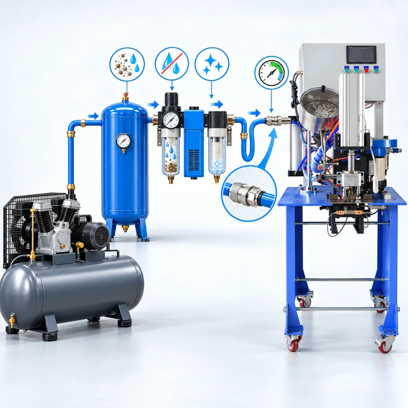
A pneumatic eyelet machine may show the correct air pressure while it sits idle, then slow down or set eyelets inconsistently when you run a production batch. The compressor gauge can look normal even though a narrow hose, restrictive coupling, loaded filter, or shared air line starves the machine during each stroke.
To plan an installation, you need the exact machine’s pressure range, air consumption, flow demand, connection details, and air quality requirements. Then you need to check them at the machine while it cycles with your real material.
This guide takes you from the supplier’s utility sheet to a practical air-supply test. It deals with the pneumatic circuit and plant infrastructure; if you are still deciding between drive systems, see our pneumatic, mechanical, and servo eyelet machine comparison.
Quick Answer: What Air Supply Does a Pneumatic Eyelet Machine Need?
There is no single pressure or compressor size that fits every model. Before you connect a machine, confirm the following for its complete configuration, including any pneumatic feeders, clamps, and accessories:
- The specified operating pressure range and minimum acceptable pressure at the machine inlet while cycling.
- Air consumption per complete cycle and the required continuous and short-duration flow at your intended production rate.
- The connection thread, supply hose internal diameter, run length, and any limits on pressure drop.
- The required air quality, filtration, drying, and lubrication arrangement, plus how condensate will be drained.
- Available compressor free air delivery at the operating pressure after other plant loads are accounted for.
Confirm these fields in writing with QC Machinery for your exact model. An idle pressure reading alone cannot establish that your factory air supply is adequate.
Start With the Exact Machine Utility Sheet
A product-category page or a different model’s manual can help you understand the equipment, but it cannot set the utilities for the machine you are buying. Request a utility sheet tied to the quotation, model, serial or drawing revision, tooling, feeder arrangement, and intended cycle rate. If you add a pneumatic washer feeder or a second head later, ask whether the original figures still apply.
| Field | What to Request | Why You Need It |
| Working pressure | Allowed inlet range and minimum pressure during production | Prevents force and timing loss without exceeding component limits |
| Air consumption | Free-air volume per full cycle or demand per minute, with test conditions | Connects machine demand to output rate and compressor delivery |
| Flow profile | Continuous demand and any short peaks from simultaneous actuators | Exposes a restriction hidden by an average flow figure |
| Connection | Port/thread type and location; fitting specification | Avoids mismatched or undersized adapters |
| Air preparation | Particle, moisture, oil, and lubrication requirements | Guides filter, dryer, and regulator selection |
| Site line | Hose bore, run length, and acceptable inlet pressure at load | Allows a realistic pressure-drop check |
Ask what the consumption number includes: the press cylinder alone, or the full machine with pneumatic feeders and air-blow functions. Also confirm the reference conditions and units. A flow figure stated as free air is not the same as the physical volume of compressed air inside a receiver or hose.
Why Idle Pressure Is Not Enough
Pressure is the available push in the air system; flow is the rate at which the system can replenish air as valves and cylinders operate. When you stop the machine, the line can recover and the regulator gauge may show the set pressure.
As soon as a cylinder strokes, the pressure at the machine can dip if the line cannot deliver enough air quickly enough. Repeated cycles can deepen that dip before the line fully recovers.
Measure at a suitable test point near the machine inlet, downstream of the plant distribution line and the relevant air-preparation equipment. If the machine has a local regulator, record both its upstream supply and regulated downstream pressure where safe access and the pneumatic diagram permit.
A slow gauge may miss a short dip; use a suitable recording gauge or pressure sensor if the symptom is intermittent. Have a qualified technician install test points and follow the machine’s isolation procedure. Never defeat a guard or loosen a pressurized fitting to obtain a reading.
A pressure loss at the compressor outlet points to a different problem than a loss only at the machine inlet. Compare readings taken at the same time and under the same production load before changing the regulator setting.
Estimate Air Demand at Your Actual Cycle Rate
Use the complete machine’s air consumption per cycle and the number of cycles you expect it to run. If both figures use the same free-air reference conditions, the first estimate is straightforward:
Average machine demand per minute = free-air consumption per cycle × cycles per minute.
For example, if a hypothetical configuration consumes 2 liters of free air per full cycle and runs 30 cycles per minute, its average is 60 liters of free air per minute. Those values are an illustration, not a QC Machinery specification or a compressor recommendation. The calculation does not show how much air the machine draws during the brief part of a cycle when several actuators move together.
Add the demand from pneumatic feeders, ejectors, clamps, blow-offs, and any other functions that the quoted per-cycle figure excludes. For a two-head arrangement, check whether the heads fire together or in sequence.
Simultaneous operation may create a higher short-term flow demand even when the same number of eyelets is produced over a minute. Record the planned maximum rate and the rate actually achieved with real material, rather than calculating from an unloaded demonstration.
When you compare this total with a compressor datasheet, use its delivered airflow or free air delivery (FAD) at the relevant operating pressure. Motor power, receiver volume, and the compressor’s maximum pressure are separate facts; none substitutes for delivered flow. Confirm the unit basis with the compressor supplier before comparing a rating in cfm with machine data in liters per minute.
Size the Compressor for the Whole Factory Load
Your eyelet station rarely owns the entire air network. Make a list of the machines and tools that can draw air at the same time, including packaging equipment, blow guns, pneumatic clamps, and a second eyelet line.
Consider normal leakage, the compressor’s control or duty limits, dryer and filter losses, and expansion you have already committed to. Ask the compressor supplier to evaluate delivered flow at the pressure you actually require while these users operate together.
A receiver can buffer a short air draw, but it cannot make up for a compressor that supplies less air than the plant consumes over time. A larger tank may delay a pressure decline during a trial and still allow the line to sag during a full shift.
Likewise, raising compressor discharge pressure to compensate for a restrictive pipe may increase energy use and expose downstream components to excessive pressure. Find the restriction and design the delivery path first.
If the plant has a central compressor, check its pressure at both load and unload conditions and record the lowest available pressure at the eyelet machine during the busiest realistic period. If a dedicated compressor is proposed, ask for its FAD curve, operating mode, receiver, and air-treatment arrangement as one package.
Hoses, Pipes, and Fittings Determine What Reaches the Machine
A correctly sized compressor can still feed a poorly supplied station. Long pipe runs, small internal diameters, repeated bends, undersized quick couplers, and partially closed valves each add resistance. The weakest opening may be a connector or filter port rather than the visible hose. The same connector thread size does not guarantee the same internal flow passage.
Trace the entire route from the compressor or ring main to the machine inlet. Record the internal diameter rather than only the hose’s outside diameter, the line length, number and type of couplers, and the pressure drop across filters and regulators during flow.
Compare those details with the machine supplier’s minimum inlet requirements and the line designer’s sizing calculation. Avoid guessing a universal hose size: the right bore depends on demand, pressure, length, and allowable drop.
A useful field clue is a machine that runs normally at a slow pace but loses stroke speed or setting consistency at full rate. Before ordering a larger compressor, have a technician check the machine inlet pressure while cycling and inspect the branch line. A restricted filter element or small quick connector can produce the same symptom as low compressor capacity.
Keep the Air Clean and Dry
Compressed air carries some combination of water, particles, and oil depending on the compressor and treatment system. Liquid water can reach valves and cylinders, contribute to corrosion, and make operation unreliable.
A water separator removes entrained droplets within its rated conditions, but it does not remove water vapor; a dryer may be needed when the site conditions and the specified pressure dew point call for one. Drain receivers and separation devices according to their manuals and check that drains function under actual load.
Ask QC Machinery for the machine’s required air-quality limits and confirm the filtration and dryer specification against the plant’s measured or documented air quality. Filter elements must be maintained: an overloaded element can cause a pressure drop at exactly the point where you need flow. Check air quality at the point of use, not only at the compressor room.
Do not add an in-line lubricator just because the machine is pneumatic. Some pneumatic components are designed for a specified lubrication method; adding oil to a circuit that does not call for it can contaminate components or workpieces.
Follow the exact model’s pneumatic diagram and maintenance instructions. If your application handles a contamination-sensitive fabric or finish, tell the supplier before agreeing on air treatment and any blow-off function.
Diagnose Air Supply Symptoms Without Assuming Their Cause
| Observed Behavior | Possible Air-Supply Cause | First Check |
| Settings weaken at full speed | Pressure drops during repeated strokes | Record inlet pressure through a normal run |
| Cylinder returns slowly | Restricted supply or exhaust path | Inspect hose, couplers, filter and valve per manual |
| Intermittent feeder timing | Shared-line pressure fluctuation | Run other air users; log pressure at the station |
| Works slowly but not at target output | Insufficient delivered flow or branch restriction | Compare FAD and machine inlet pressure at load |
| Condensate appears in the line | Drain, separator, or dryer problem | Inspect treatment equipment and point-of-use air |
These observations are clues, not proof. Worn dies, incorrect eyelet and washer combinations, misalignment, valve faults, seals, sensors, and feeder setup can create similar symptoms.
If pressure and flow remain within the agreed limits during the fault, move to the appropriate machine and process checks in the eyelet machine troubleshooting guide. Do not compensate for an unresolved defect by raising pressure above the allowed range.
Verify the Supply Before You Accept the Installation
Treat air supply as a measured site condition, not a promise from the compressor nameplate. This focused check complements the broader eyelet machine acceptance test checklist, which also covers safety, feeding, finished eyelets, output, and documentation.
- Match the installed machine, feeders, and options to the current utility sheet. Record the approved pressure range, flow and air-quality requirements, and exact test points.
- With the equipment safely connected, note compressor or header pressure, upstream pressure at the station, and regulated pressure at the machine while idle.
- Run the real eyelets, washers, and materials at the intended production pace. Record the lowest relevant pressure during cycling and any alarm, delayed return, misfeed, or setting change.
- Repeat with the other normal air users on the branch operating together. Test the most demanding approved configuration, including pneumatic accessories and simultaneous heads where fitted.
- Inspect leaks, couplers, regulator response, filter pressure drop, condensate collection, and drains. If readings fail the agreed limit, correct the cause and repeat the same test.
- Keep the readings, cycle rate, air-treatment details, production samples, and any corrective action in the site-acceptance record. Agree on pass criteria with the supplier before the run.
Where the factory acceptance test took place on the supplier’s air system, do this check again after installation. A passing FAT does not prove that a longer hose or crowded plant header will deliver the same conditions at your site. For a more complete output trial, see how to verify eyelet machine cycle time and real output.
What to Send QC Machinery Before Installation?
A useful inquiry includes the model and quoted configuration; eyelet and washer sizes; material stack; intended cycles per minute; number of heads and pneumatic accessories; compressor model and delivered flow at operating pressure; receiver capacity; normal and lowest header pressure; line length and internal diameter; fittings and couplers; other users on the same branch; dryer, filter, regulator, and drain details; and any cold or humid site conditions. Include a pneumatic drawing or photos of the installed branch if available.
If you do not have per-cycle air consumption or an allowable dynamic pressure limit, ask QC Machinery to confirm them for the exact machine and test configuration. You can use the pneumatic grommet press machine range to identify the relevant machine family, but the utility sheet for the purchased configuration should govern the installation.
Frequently Asked Questions
What Pressure Does a Pneumatic Eyelet Machine Need?
Use the permitted operating range for your exact model and check the minimum pressure at the machine during repeated cycles. A number printed for a different press cannot establish the requirement for your machine.
Can I Choose a Compressor From Its Tank Size?
No. Tank volume helps buffer short demands, while compressor FAD indicates how much air the unit can deliver over time at a stated pressure. Check both against the whole plant load and the machine’s cycling demand.
Why Does the Gauge Look Normal Until the Press Runs?
The line can recharge while the machine is idle. When cylinders stroke, demand rises and restrictions or insufficient delivered flow can make inlet pressure fall—measure during production, preferably with a recorder if dips are brief.
Does Every Pneumatic Eyelet Machine Need an Air Dryer or Lubricator?
Air treatment depends on the model’s specified air quality and the site’s conditions. A separator alone does not remove vapor. Do not install a lubricator unless the exact machine instructions call for it.
Where Should I Measure Pressure?
Measure at the machine inlet and, where the pneumatic diagram allows, around the regulator and air-preparation group. Compare this with header pressure under the same load so you can locate the pressure loss.
Confirm the Air System Before Production
Send QC Machinery your machine configuration, target cycle rate, and factory air-system details before installation. Ask for the corresponding utility sheet and record pressure at the machine while you run production materials at the planned rate. This gives you a clear basis for line sizing, compressor review, and site acceptance instead of relying on an idle gauge reading.