

You can produce a perfectly printed retail display and still lose the job at the finishing stage. A crushed corner, an eyelet that marks the artwork or a pair of holes that do not align with the hanging rail can turn finished stock into rework.
When you choose eyelet machines for retail displays and signboards, you need to look beyond whether the machine can set an eyelet. You need a process that preserves the panel, locates each hole correctly and produces an attachment point suited to the actual mounting arrangement.
That becomes especially important when you move from flexible graphics to corrugated plastic, foam-centered board or laminated sheets. Your substrate may resist bending yet compress under the setting tools. Your printed surface may look durable yet scratch when you slide it across the table.
This guide helps you plan that production process. You will learn what to test, how to handle rigid substrates and what to include in a machine inquiry without assuming that one setting method works for every display material.
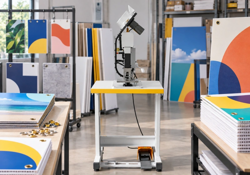
Start With the Display and Its Mounting Arrangement
Before you specify a machine, establish what the finished display has to do. You may be producing suspended promotional panels, shelf-side signs, temporary point-of-sale displays or interchangeable graphics for a retail fixture. Each arrangement gives you a different attachment geometry and different handling demands.
Work from the approved display drawing rather than choosing a familiar eyelet first. Confirm whether a cord, hook, cable tie or proprietary fitting passes through the opening. Check the required clearance, the direction of pull and whether the rear side of the setting remains accessible after assembly.
You should also ask whether an eyelet is necessary. A frame, clamp or engineered mounting hole may suit the panel better. An eyelet can reinforce an opening, but you should not treat it as a substitute for a suitable substrate or an approved support system.
For overhead displays, you need the complete mounting arrangement reviewed against the applicable site and customer requirements. A successful machine trial does not establish that a suspended sign is safe. You still need appropriate assessment of the panel, hardware, supports and installation.
Separate Flexible Graphics From Rigid Sign Panels
If your factory already finishes banners, you have useful experience with hardware feeding and repeatable setting. However, you should not carry the same setup straight across to a rigid signboard.
A flexible graphic can lie over a support surface and move around the tooling. A rigid panel needs clearance for its full footprint. It may bridge across the table, contact the machine frame or place leverage on the hole when the operator lifts the opposite edge.
You also need to distinguish the total board thickness from the material that actually supports the eyelet. On a hollow or foam-centered panel, much of that thickness may be compressible space rather than solid material. A setting that appears tight can conceal crushed structure beneath the flange.
Keep separate approved recipes for flexible and rigid jobs. Your board-grade specification, hole preparation, tooling and support arrangement should identify the rigid-panel process clearly, even if you use the same machine for both.
Check Your Actual Substrate Construction
Corrugated Plastic Panels
With corrugated plastic, inspect both outer skins and the internal flutes. Record the board grade, thickness, flute direction and whether the attachment sits near a trimmed edge. Your result may change when the hole crosses a different part of the hollow structure.
During trials, look for local collapse, distorted skins and cracks around the opening. Cut open a sacrificial sample if you need to see what the setting has done inside the panel. A neat front face alone may not reveal a damaged core.
Do not assume that a wider flange solves every problem. It may spread contact over a larger area, but you still need to verify the resulting load transfer and the condition of the material underneath. If you add a backing piece or reinforcement, test that complete construction rather than the bare board.
Foam-Centered and Paper-Faced Boards
With foam-centered boards, watch for indentation under the flange and separation between the facing and core. The facing may tear before the eyelet itself fails. If you laminate the print, examine the laminate around the hole as well.
Your trial should use the same printed, bonded and finished construction that reaches the customer. An unprinted offcut cannot show whether the coating is marked, the adhesive separates or the finished edge becomes vulnerable during handling.
If the display encounters humidity, cleaning or outdoor exposure, agree suitable conditioning with your customer. You should not infer wet-service suitability from a successful test on dry stock.
Solid Plastics and Other Rigid Sheets
For solid plastic sheets, identify the polymer and grade instead of using “plastic board” as the material specification. Brittle sheets may crack during punching or setting, while other grades may deform or develop stress damage that appears later.
You may need to drill, route or otherwise prepare the opening in a separate operation. You should not assume that a self-piercing eyelet process is appropriate for acrylic, composite panels, metal-faced sheets or any unfamiliar rigid material. Obtain sample evidence for the proposed process before you commit to equipment.
If you cannot obtain an acceptable result without cracking, crushing or unstable retention, reconsider the attachment design. Buying a stronger machine does not resolve an unsuitable board-and-hardware combination.
Control Hole Preparation Before You Adjust the Setting
Your eyelet can only work with the opening you give it. Check the hole diameter, shape, edge condition and location before you change the setting force or stroke.
On rigid stock, a rough opening can leave chips beneath the flange. An oversized opening can reduce the material available to support the hardware. An undersized opening may require excessive insertion force and distort the panel before setting begins.
If your proposed machine punches and sets in one cycle, verify that operation on your actual board. Check both faces and the removed waste. You need evidence that the process forms a suitable opening consistently, not just that the eyelet can be pushed through.
For materials that need a separate preparation stage, review when pre-punching is mandatory for eyelets before you compare machine configurations.
Keep the hole-making method in the production specification. If a subcontractor supplies pre-punched panels, agree their hole tolerances and inspection method. Otherwise, your setting station may inherit variation it cannot correct.
Match the Eyelet and Tooling Without Crushing the Panel
Specify the full hardware combination: eyelet dimensions, barrel geometry, material, finish and any approved washer or backing component. Then confirm that the forming tools match it.
You need enough barrel engagement to create the intended setting without forcing the flange into the board. Do not select barrel length from nominal panel thickness alone. Your finished stack may include print layers, laminates, reinforcement or a backing washer, and its behavior under compression matters.
Use the principles in matching eyelet size, washer size and die sets to define the tooling combination, then qualify it on the signboard construction.
Judge the result against agreed criteria rather than a universal “tightest possible” rule. Too much compression can damage the board. Too little can leave an unstable attachment. If rotation matters to your mounting arrangement, define an acceptable limit and test method instead of assuming that every application requires zero movement.
You should also confirm what the customer sees. Metal and plastic hardware can produce different visual results, but neither is automatically suitable for every printed panel. Check flange coverage, finish consistency, rear profile and any marks left by the tools.
Register Holes to Finished Edges and Artwork
For retail campaigns, location errors often cause more trouble than obvious setting defects. You may have a clean eyelet in the wrong place, making a panel hang crooked or preventing two mounting points from aligning with the fixture.
Define your positioning datum from the approved drawing. In many jobs, you will locate from finished trimmed edges; in others, you may need a specified relationship to artwork or fixture features. Resolve that choice before production.
Do not let operators measure from whichever edge is easiest to reach. If trimming varies, a positioning system that ignores the final panel dimensions can produce inconsistent margins. Check the relationship between the print, cut edge and hole pattern on a finished first article.
For paired holes, inspect the spacing between them as well as each hole’s distance from an edge. For asymmetrical panels, use a fixture or orientation cue that prevents mirrored patterns when you turn the workpiece over.
If you process several sizes in one campaign, label your stops, templates or stored positioning programs by SKU and revision. A correct setting recipe does not prevent an operator from using the wrong hole pattern.
Support Large Panels and Protect the Printed Face
Place your support table at a height that keeps the panel level with the working area. If the far edge drops, you can bend the board or put leverage on the newly formed attachment as you move to the next position.
Trial your largest panel, not only a small coupon. Check how you load it, rotate it and reach every hole without striking the machine frame. Include the space needed for incoming sheets, finished panels and an operator handling the work safely.
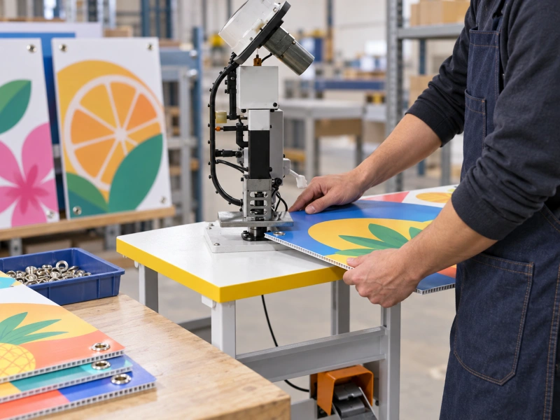
When an attachment sits farther inside the panel, check how throat depth affects eyelet machine selection using your actual panel dimensions and hole locations.
Use a clean support surface that suits the print finish, and keep chips or punched waste away from it. Trapped debris can scratch graphics when you slide the panel. If you use a protective film, verify whether it remains during setting and whether removing it later disturbs the eyelet area.
Do not remove guards or defeat safety devices to make a large board fit. If your handling plan requires that, you need a different approved configuration or workflow.
Choose Automation Around Your Retail Job Mix
Your best configuration depends on the work arriving at the station. A short campaign with frequent changes in board size and hardware may favor a flexible setup. A long run of one approved construction may justify more automated feeding or positioning.
Separate hardware feeding from workpiece positioning in your inquiry. Automatic eyelet feeding does not necessarily mean automatic panel transport, automatic hole location or automatic handling of backing components. Ask exactly which tasks the quoted configuration performs.
Measure output through the whole job: loading the panel, positioning it, setting every attachment, checking it and transferring it without damage. A fast setting cycle tells you little if the operator spends most of the time managing a large printed board.
Request a trial that reflects your normal SKU sequence. Include a change between two representative constructions and record the adjustment time, confirmation checks and first-good-piece result. You will then have a more useful basis for comparing configurations than headline cycle speed.
Control Mixed-SKU Campaign Production
Build a job packet that keeps the approved drawing, material specification, hardware code and setting recipe together. Retail promotions can involve similar-looking panels with different mounting patterns, so you need identification at the station.
At a changeover, separate leftover hardware and panels from the previous job. Confirm the tooling, locator settings and print orientation before you release the next batch. Keep a marked first article or approved sample where you can compare it without confusing it with saleable stock.
Count good finished panels, not just machine cycles. If you record rejects, distinguish hole-preparation defects, setting defects, positioning errors and surface damage. That distinction helps you address the stage responsible rather than adjusting the press for every problem.
If you need to remake one SKU, retain enough traceability to reproduce its approved setup. Your material lot, hardware lot, recipe revision and inspection record can help you understand whether replacement panels will match the original delivery.
Run a Production-Representative Sample Trial
Send complete examples of the job, including the printed finish and the actual mounting hardware where available. Include your thinnest and thickest approved constructions, your most demanding hole locations and a full-size panel that exposes handling constraints.
Use the sample preparation guide for eyelet machine trials to prepare a clear test package rather than sending unidentified scraps.
Agree the acceptance criteria before the supplier runs the trial. Ask for the proposed hole-making method, tool combination and setup to be recorded alongside the samples. Photographs are useful, but you should inspect physical samples when hidden core damage or rear-side geometry matters.
Include the intended hook, tie or fitting in your assembly check. You need to know whether it passes through cleanly, seats correctly and loads the attachment in the direction you expect. Do not substitute an unrelated pull direction just because it is easier to test.
For displays under sustained or repeated loading, agree suitable duration, cycling and environmental conditioning with the responsible customer or engineer. You should not invent a universal pull-load threshold for all retail signs.
Define Acceptance Before You Release the Batch
Your inspection plan should cover both appearance and function. Specify what you accept around the flange, on the rear face and at the finished edges. State the allowed positioning variation and how you measure it.
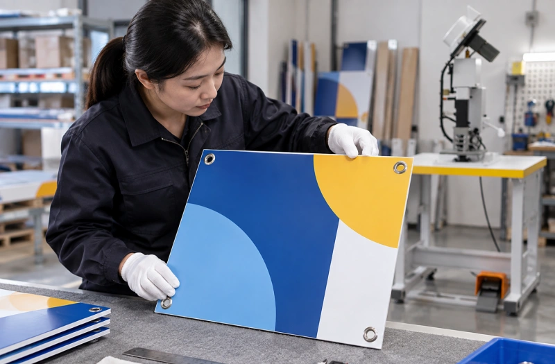
Include checks for cracks, crushed cores, facing separation, trapped debris and unacceptable print marks. Where a defect can remain hidden, establish an appropriate destructive inspection method during qualification or as required by your quality plan.
Keep assembly validation distinct from visual inspection. A panel can look acceptable yet fail to fit the fixture or retain its attachment under the agreed conditions. Record the failure mode if a trial fails: board tearing, core collapse, hardware deformation or another mechanism.
Only release the construction and process you have actually qualified. A different board supplier, thickness, print treatment or eyelet can require another review even when the finished sign looks similar.
Prevent Damage During Packing and Store Distribution
Inspect how the eyelet sits in a stack of finished panels. A protruding rear-side profile may mark the printed face of the panel below it. You may need separators, a revised stack orientation or a different approved packaging arrangement.
Check your packing method with production samples, especially where panels travel through distribution centers before reaching stores. Edge knocks and rubbing can damage an attachment area that passed inspection at the machine.
Provide clear mounting information with the job where your customer requires it. You should distinguish approved use from improvised installation, particularly for suspended displays. Your factory setting quality cannot control how a store later attaches the sign.
What to Include in Your Machine Inquiry
Give the supplier enough information to evaluate the process, not just a request for a machine that works on signboards. Include:
- Your substrate grade, full layer construction and thickness range.
- Your smallest and largest panel sizes, with approved hole drawings.
- Your eyelet, washer or backing-component specifications and mounting fittings.
- Your print finish, protective-film arrangement and acceptable surface condition.
- Your expected SKU mix, batch sizes and required finished-panel output.
- Your agreed inspection, assembly-test and conditioning requirements.
- Your workspace, utilities and panel-handling constraints.
Ask QC Machinery to review a configuration against that package and representative samples. Keep the quotation linked to the trialed construction, tooling and handling arrangement so you know what has been evaluated and what still needs confirmation.
FAQ
Can You Use a Banner Eyelet Machine for Rigid Signboards?
You may be able to, but you need to confirm the particular configuration on your board, hardware and hole pattern. Check hole preparation, setting quality, throat clearance and full-panel support. Successful banner work alone does not establish rigid-board compatibility.
Can You Punch and Set Corrugated Plastic in One Operation?
Some equipment-and-hardware combinations may support that process. You still need trials on the actual board grade and construction. Inspect both skins and the core; do not approve the process solely because the ring looks neat from the front.
Should You Choose Plastic or Metal Eyelets for Printed Displays?
You should choose based on your appearance, mounting, forming and end-of-life requirements. Trial the complete hardware-and-board combination. Do not assume that plastic hardware makes the whole display recyclable or that metal hardware automatically gives better retention.
How Do You Prevent Crushed Foam Board Around an Eyelet?
You need to review the hole, hardware geometry, forming tools and local support together. Reinforcement or another attachment design may be necessary. Reducing the setting pressure alone may leave loose hardware without solving the underlying weakness.
What Determines the Hole Spacing on a Retail Sign?
Your approved display and mounting design determine it. You need the relationship to the fixture, finished edges and artwork, plus appropriate positioning tolerances. You should not apply a standard banner spacing rule to every rigid retail panel.
Build Your Process Around the Finished Display
You get a more dependable result when you treat eyelet setting as part of display manufacture rather than a final isolated operation. Your substrate, opening, hardware, location, support table and packing method all affect the delivered panel.
Send QC Machinery your finished-panel drawing, material construction and representative samples before you choose a configuration. You can then evaluate the machine against the job you actually need to produce: clean printed faces, repeatable mounting points and a qualified attachment process for your retail campaign.