

When you set an eyelet into a narrow strap, you have little room for error. A small sideways shift can leave too little webbing beside the hole. A folded end can put one side of the washer over a thick seam while the other side sits on a single layer. The finished eyelet may look straight, yet the strap can twist or tear when you load it.
Choose eyelet machines for webbing straps and tie-downs based on this narrow-material geometry. Start with the approved attachment design, then establish how you will locate, support, and inspect each strap. Machine compatibility needs to be demonstrated on your actual webbing and hardware combination.
This guide covers purpose-designed eyeleted webbing components, including retaining straps, cover attachment tabs, and engineered tie-down components where the design specifies an eyelet. It does not provide instructions for adding holes to existing rated cargo straps.
You will learn how to control lateral position, repeated-hole spacing, folded constructions, and long flexible tails while keeping machine approval separate from product load-rating approval.
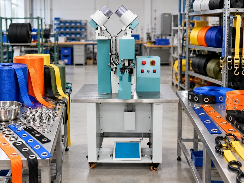
Decide Whether the Strap Should Have an Eyelet
Mark the eyelet location on the product drawing and state its function. You may be guiding a cord, providing a removable attachment point, or reinforcing an opening that receives repeated contact. Those duties require different opening sizes and different tests.
For cargo restraint, identify the complete load path before choosing equipment. If you punch through the part of the webbing that carries tension, you change its construction. You cannot assume that the original webbing strength or the finished strap rating remains valid after eyeletting.
Do not punch an existing rated ratchet strap to create another fixing point, and do not fit an eyelet as a repair for a damaged hole. Refer damaged restraint equipment to its manufacturer’s removal and replacement instructions. New eyeleted restraint designs require approval of the complete assembly, including the modified webbing, connections, and intended loading conditions.
You should also distinguish cargo restraint from lifting, towing, recovery, and personal protection. Approval for one duty does not establish suitability for another. This application guide is about manufacturing the specified eyelet feature, not assigning a working load limit.
If the proposed opening is unsuitable for the load path, review a sewn loop or another engineered fitting with the responsible designer. A more powerful setting machine cannot make an inappropriate attachment design acceptable.
Specify the Webbing as a Narrow Woven Component
Give your machine supplier more than a material name. Record the fiber type, weave, finished width, thickness, and surface treatment. Include the supplier’s webbing code so a trial on one grade is not later mistaken for approval of every similar-looking roll.
Polyester, nylon, and polypropylene constructions should not share a setting recipe merely because they have the same width. Weave density, coating, and compressibility can change how the hole forms and how the hardware grips the stack. Obtain sample evidence rather than choosing by fiber name alone.
Identify whether you use flat or tubular webbing. A tubular construction introduces two walls that can shift relative to each other. If your design passes an eyelet through both walls, check their alignment and the intended effect on the tube. If only one wall is involved, confirm that the tooling can access and support it without catching the other.
Measure the width variation in production stock. A guide designed for the nominal width can pinch a wider lot or allow a narrower lot to wander. Your positioning plan needs to accommodate the approved material range while still meeting the hole-location limits.
Include curled edges, roll set and any thickness differences at the selvages, which are the woven side edges. These features can prevent the strap from lying flat even when the central area looks uniform.
Check Side Clearance and End Clearance Separately
On a narrow strap, the hole diameter is only part of the geometry. Check the footprint of the front flange and the rear washer, where used, as well as the material remaining between the opening and each edge.
Define lateral position from the approved drawing. You may need a centered opening or an offset attachment, but either arrangement needs a controlled relationship to both side edges. If you locate from only one edge, width variation changes the remaining material on the other side.
Check longitudinal clearance from the finished end separately. A hole can be centered across the strap yet too close to its cut end, fold or stitched termination. Record the end datum clearly, especially where the finished length includes a folded return.
Do not apply a universal minimum edge distance to every webbing grade. Your opening size, weave, reinforcement and load direction determine what you need to qualify. A flange that fits within the strap width does not, by itself, prove that enough load-carrying material remains.
If the hardware footprint nearly fills the strap width, ask the designer to review the joint before you finalize tooling. A larger washer may overhang the sides or leave a stiff edge that rubs against adjacent webbing.
Control Centering Without Stretching the Strap
Your fixture should present the strip square to the tools without pulling it into a different shape. A narrow guide channel, paired side guides, or another approved locating arrangement may help, but you need to prove the method across the full approved width range.
Use the trial to check whether the guides center the strap, reference one edge, or merely prevent gross sideways movement. Those functions are not interchangeable. If your drawing specifies a centerline, verify the finished hole’s relationship to both edges.
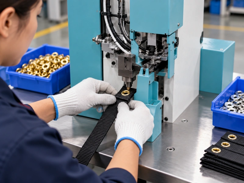
Avoid using hand tension as an uncontrolled positioning aid. Pulling a flexible strip straight can alter its dimensions; it may relax after setting and move the hole away from the intended position. Define the presentation condition and reproduce it during inspection.
For repeated holes, choose whether you locate every position from a common datum or index from one position to the next. Successive indexing can accumulate error. Inspect the first-to-last relationship as well as the local pitch between adjacent holes.
Check that a held or previously eyeletted section does not tilt the next setting point. A fixture recess or separate support may be necessary to accommodate projecting hardware. Keep any proposed fixture compatible with the machine’s guarding and operating instructions.
Qualify Folded Ends and Reinforcement as Complete Joints
If your design includes a folded end, reproduce the actual return length, layer sequence, and stitching in the trial samples. Two loose pieces of webbing stacked on the bench do not represent a stitched fold under tension.
Pay particular attention to the transition from single to multiple layers. If that transition sits under the flange or washer, the tools can clamp an uneven stack. You may see a tilted eyelet, incomplete seating, or concentrated pressure on the thicker side.
Keep the eyelet location relative to the seam in the product specification. Do not let production move the hole away from a difficult stitch crossing without design approval. That shift changes the attachment geometry even if it improves the appearance.
Reinforcement should have a defined function and attachment method. A backing patch can create a wider local seat, but its seam or bond must transfer the intended force into the strap. An eyelet that stays in the patch while the patch separates from the webbing is still a failed assembly.
Assess the stiffness transition around the reinforced area. During bending, the flexible strip may repeatedly flex at the edge of the hardware or patch. Include that movement in your qualification where it reflects actual service.
Choose Hole Preparation for the Actual Weave
Compare a separately punched opening with a combined pierce-and-set process where the proposed hardware and machine configuration support it. Neither route should be approved on the basis of press force alone.
With pre-punching, you can inspect the bare opening before installing hardware. Check for incomplete cuts, pulled yarns, and deformation extending beyond the intended hole. Then verify that moving the strap to the setting station does not stretch or misalign the opening.
With a combined process, examine what happens to the cut material. Trapped yarns or waste can interfere with formation or conceal damage beneath the flange. Include both the densest approved weave and the most compressible construction in the trial.
Review the pre-punching decision guide for the general process choice. Your webbing-specific approval should still record the width, weave and exact reinforcement stack.
If you consider thermal hole preparation for synthetic webbing, obtain approval of the process and its effect on the joint. A sealed-looking opening does not prove that heat has preserved the required strength. Do not transfer hot-cutting assumptions to unfamiliar fibers or coatings.
The broader guide to preventing fraying around eyelet holes covers general edge control. For narrow straps, add an inspection of the remaining yarns beside the opening and at the finished end.
Match Hardware to the Compressed Stack
Start with the opening required by the intended cord, pin, or fitting. Then specify the eyelet dimensions, material, and finish, plus the washer or backing component required by your approved system.
Barrel length needs to suit the actual stack and forming process. Folded webbing can compress substantially, and recovery after setting can change the apparent tightness. Check the result after the agreed settling period as well as immediately after the cycle.
Use the eyelet and die matching guide to identify the component combination. For this application, include the maximum rear-hardware footprint that the narrow strip can accommodate.
Do not select toothed or spur washers simply because you want more grip. Their interaction with the weave requires review: a component that resists movement may also damage yarns. Inspect sectioned samples where hidden contact matters, and compare the complete joint under its intended loading.
Check the formed inside edge against the mating fitting. A hook or cord may contact only one side of the opening in use, creating a different condition from a symmetrical bench pull. Include finish wear and rubbing where they are relevant to the product specification.
Manage Long Tails Before You Increase Automation
The strip may be narrow, but its length can dominate handling. An unsupported tail can drag across the bench, snag on another part or pull the setting point out of the fixture.
Plan a clean, supported route for incoming and finished straps. If you feed from a roll, review unwind drag and tension changes as the roll diameter decreases. If you process cut pieces, separate the tails so they do not become tangled during loading.
Confirm the stage at which you set the eyelet. A blank strap may lie flat, while a strap with a buckle, sewn loop or other fitting may need extra clearance. Trial the assembled condition that actually reaches the station.
Ask what the quoted automation includes. Automatic eyelet feeding, washer feeding, and automatic strip positioning are separate functions. A hardware feeder does not necessarily measure the strap length or control the hole pitch.
For a proposed indexing system, check grip on coated and uncoated stock, stopping accuracy, and relaxation after feeding. Include startup, restart, and the transition between lots. Your useful output is the number of accepted straps, not the number of press cycles recorded.
Keep Three Types of Testing Separate
Longitudinal Strength of the Modified Strip
If the strap carries tension along its length, assess the effect of the specified opening on that load path. Test the relevant modified construction under the approved method. Unpunched-webbing data alone cannot establish the strength of an eyeleted component.
Retention of the Eyelet Connection
You also need to know how the fitting loads the eyelet. Pulling through the eyelet opening can produce bearing, tearing, or peeling that differs from a longitudinal strip test. Match the connector, load direction, and support geometry to the intended use.
Record the failure mode alongside the measured result. Hardware pull-through, yarn rupture, reinforcement separation, and hardware deformation point to different design or process issues. Do not combine unlike test results into one unexplained strength figure.
Performance of the Finished Assembly
For a tie-down design, the complete assembly includes more than the eyelet. Stitching, the buckle, end fittings, and other connections need evaluation under the applicable product requirements. Agree on the test scope, acceptance limits, and rating basis with the responsible product engineer.
Where service involves repeated tension, flexing, abrasion or environmental exposure, include the relevant conditions in qualification. Do not assign a working load limit from a brief hand pull, a neat flare or the breaking strength of raw webbing. Machine sample approval confirms the setting process only within its evaluated scope.
Approve Representative Samples Before Production
Send the supplier samples of the finished construction, not just a short length from a convenient roll. Include the narrowest approved width, the thinnest and thickest stacks, folded ends, and the most difficult hardware-access location.
Use the sample preparation guide for machine trials to label the package. For straps, add the processing face, longitudinal datum, permitted hole pattern and whether the eyelet participates in a load-bearing function.

Agree on the dimensional and visual acceptance criteria before testing. Ask the supplier to retain the machine configuration and tool identification with the sample results. Keep setting evidence separate from any independent assembly-test records.
Inspect the finished joint from both faces. Check centering, end clearance, damaged yarns, incomplete seating, and objectionable sharp edges. For multilayer constructions, verify that every required layer is captured and that no prohibited seam transition sits beneath the hardware.
Retain an approved sample and setup record by product revision. A change in webbing weave, coating, reinforcement or hardware can require another review even when the new parts have the same nominal dimensions.
What to Include in Your Machine Inquiry?
Give QC Machinery enough information to evaluate the narrow-strip process. Include:
- Your application and the function of the eyeletted point.
- Your webbing code, fiber, weave, width range, and thickness range.
- Your folded or reinforced construction, including relevant seams.
- Your eyelet and washer drawings, material, and finish.
- Your hole pattern, side clearance, end datum, and positioning limits.
- Your longest strap and any fittings present during setting.
- Your batch sizes, changeovers, and required output of accepted straps.
- Your inspection criteria and separately defined product qualification requirements.
Ask that the quotation identify the trialed hardware, hole-making route, and positioning arrangement. If automated indexing is proposed, request a demonstration using your actual strip construction and hole pattern. Confirm which remaining application questions need evidence before purchase.
Frequently Asked Questions
Can You Add Eyelets to a Finished Rated Ratchet Strap?
You should not modify it to create another attachment point. An added opening changes the rated construction, and an eyelet does not restore the original rating. Obtain a purpose-designed assembly from the responsible manufacturer instead.
Can One Fixture Handle Several Webbing Widths?
It may, if its locating method supports the approved width range and required datum. Trial the extremes and verify both side clearances. An adjustable guide that prevents wandering is not necessarily a centering fixture.
Should You Choose a Larger Washer for Better Retention?
Not automatically. Check its footprint, support and interaction with the weave. If it overhangs the strip or creates a damaging stiffness transition, a larger component can introduce another problem. Approve the complete joint through the specified tests.
Can You Use the Same Setup for Flat and Folded Webbing?
Only after qualifying both constructions. A folded stack changes thickness, compression and seam geometry. You may need different hardware, tooling or settings even when the underlying webbing grade is unchanged.
Does Automatic Hardware Feeding Control Hole Spacing?
Not by itself. You need a separate, defined positioning or indexing method. Ask the supplier to distinguish hardware delivery from strip transport and demonstrate the complete operation.
Choose Equipment Around the Approved Strap Design
You get a more useful machine specification when you define the narrow-strip geometry first. Control where the hole sits, how the full stack is supported, and what happens to the remaining webbing under the intended load.
Send QC Machinery your strap drawings, hardware specifications, and representative samples for a configuration review. Keep the machine trial tied to that construction, then complete the separate assembly qualification required for your product and market.