
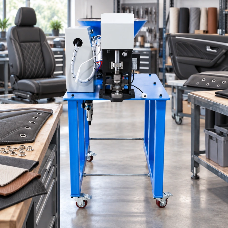
An eyelet process for an automotive interior part has to satisfy more than a visual check. The opening must stay in the drawing location, the hardware must form without sharp edges or loose movement, and the press must leave the visible surface and the hidden material stack undamaged. The result also has to remain repeatable when material, hardware, and production lots change.
You should therefore specify the machine based on an approved component and its customer requirements. A fabric coupon, a general statement such as “suitable for upholstery,” or a machine video without your parts does not establish automotive compatibility. Use the actual cover, trim panel, or accessory construction, the released eyelet and washer, the relevant drawing revision, and the required validation plan.
This guide explains that application process. It does not claim that one machine, eyelet, or setting is approved for every vehicle interior. Your customer, engineering team, and quality system must define the release criteria for the specific part and program.
The Quick Answer
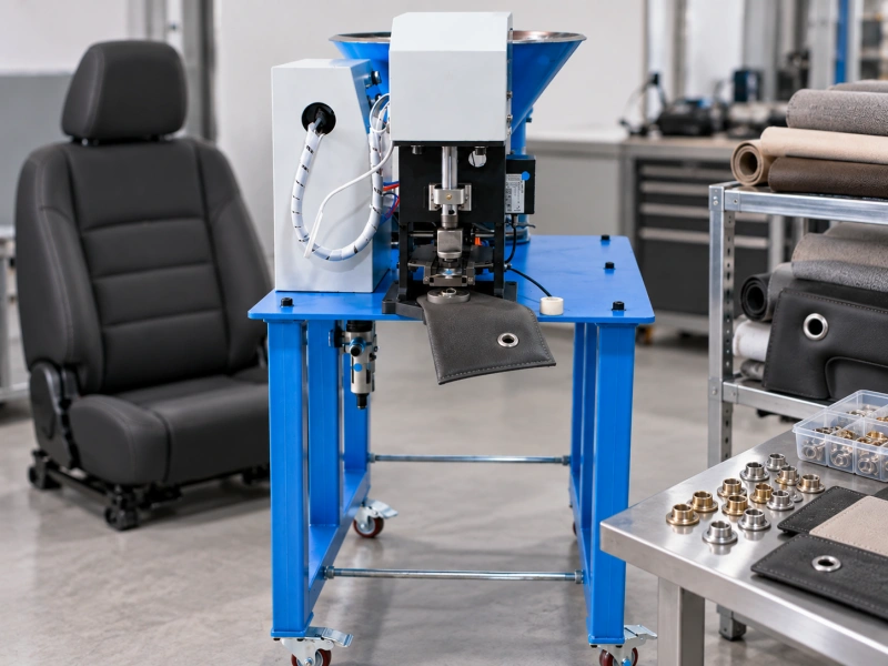
Choose an eyelet machine for automotive upholstery only after you have confirmed the eyelet location is permitted, defined the complete local material stack, and recorded the exact hardware and acceptance requirements. The machine must reach and support the real part, protect every visible surface, form the approved eyelet consistently, and provide the process controls your customer expects.
A hand-loaded powered or semi-automatic system can be practical for development, service parts, and mixed trim programs. Automatic feeding and dedicated fixtures become useful when the hardware, part geometry, and run length are stable. In both cases, approve the process with representative parts and production hardware lots. Do not select from no-load cycle speed or maximum force alone.
Confirm Where an Eyelet Is Allowed
Start with the product drawing and bill of materials. Identify why the eyelet exists, what passes through it, which surface is visible, and whether the location affects occupant safety or another regulated function.
Some trim openings provide a decorative finish, guide a cord, reinforce a service opening, or help attach a removable accessory. Other locations can sit near airbag deployment paths, restraint systems, seat structures, wiring, or pedal controls.
Do not introduce or relocate an eyelet in a safety-relevant zone without written engineering and customer approval. Treat airbag seams and covers, seat-belt and child-restraint anchor areas, structural seat components, pedal-area floor-mat retention, and critical electrical routing as controlled applications. A clean-looking eyelet does not prove that the surrounding system will perform as intended.
If the product is for the United States, interior materials may fall within the scope of FMVSS No. 302. Other markets, vehicle makers, and tiers may apply different flammability, material, appearance, emissions, corrosion, or quality requirements. The eyelet machine itself does not certify the finished component. Your release plan must identify which requirements apply and who approves the evidence.
| Possible component area | Application question | Evidence needed before release |
| Seat cover or soft trim | Is the opening decorative, a lace or cord guide, a service feature or part of an attachment system? | Released drawing, approved stack, eyelet specification, surface standard, and confirmation that the location does not interfere with an airbag or restraint function. |
| Door and side trim | Can the eyelet be supported without marking the visible face or damaging foam and substrate? | Class A appearance criteria where applicable, hidden-side clearance, fixture datum, and an approved assembled-part trial. |
| Headliner and pillar trim | Is the location clear of curtain-airbag deployment and head-impact requirements? | Written program approval and a defined validation plan. Do not infer suitability from a similar textile part. |
| Cargo and trunk trim | Does the eyelet guide, drain, retain, or reinforce, and what load direction applies? | Drawing location, service-load method, corrosion and appearance requirements, plus the actual liner or organizer assembly. |
| Floor mat or floor trim | Is the opening part of the vehicle retention system or close to pedal travel? | Vehicle-specific retention design and approval. Do not substitute generic hardware or change the location. |
| Aftermarket interior accessory | Which vehicle zones and customer claims does the accessory affect? | Fitment review, intended-use limits, material and hardware approval, and a documented risk-based test plan. |
Build the Specification From the Complete Trim Stack
Record every layer at the eyelet position. Automotive soft trim may combine woven or nonwoven fabric, leather, synthetic leather, foam, scrim, backing cloth, adhesive, edge binding, reinforcement, and a local overlap. A hard-backed trim part may add a molded substrate or a clip feature close to the setting point. Measure the minimum and maximum finished stack at the actual location.
Nominal thickness does not describe how the stack behaves under the dies. Foam compresses and recovers. Adhesive can squeeze or contaminate a cutting edge. Perforated or embossed faces can mark more easily than a plain surface. A laminated construction can separate even when the eyelet appears tight. Send the thinnest, thickest, softest, and firmest approved combinations to the trial.
Use parts from the intended production process. A hand-cut development sample may differ from a molded, laminated, sewn, or heat-conditioned component. If the eyelet is installed after the cover has been shaped or attached to a substrate, test it in that same condition. Access and support often change after assembly.
Control the Eyelet, Washer and Finish
Specify the eyelet by part number and dimensions. Record the barrel outside diameter and length, flange diameter and profile, material, hardness or forming behavior where controlled, surface finish, and allowable variation. For a washer, record its inside diameter, outside diameter, thickness, profile and orientation. Supplier trade names are not a dependable tooling definition.
The barrel length has to suit the compressed material stack and the required formed profile. Extra setting force cannot replace missing barrel length. An unnecessarily long barrel can buckle, split, leave excess projection, or damage a soft backing. Match the complete hardware system before selecting the dies. QC Machinery’s eyelet washer and die matching guide explains the measurement sequence.
Automotive requirements can also address corrosion, finish color, gloss, coating adhesion, restricted substances, odor, fogging, or contact with neighboring materials. Which checks apply depends on the vehicle program and component.
Obtain the released specification and material declarations from the responsible customer and hardware supplier. Do not describe an eyelet as automotive grade unless the exact part and evidence support that statement.
Protect the Visible and Hidden Surfaces
Many interior components have a visible face that the customer will inspect under defined lighting and viewing conditions. The upper die, lower support, guide, and operator handling can all create dents, gloss changes, scuffs, oil transfer, or pressure rings. Establish the approved appearance zone and limit the sample before the machine trial.
Use polished, correctly profiled dies and a clean support surface. A replaceable non-marking pad may help on soft faces, but it must not reduce alignment or allow the stack to tilt. Guides should locate the part without rubbing a finished edge. If the component has grain, perforation, or stitching near the hole, include those details in the sample because they can change both appearance and material strength.
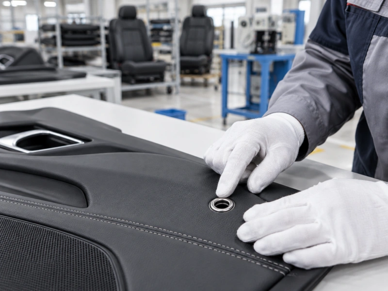
Inspect the hidden side as carefully as the face. A sharp barrel edge can cut foam, backing cloth, wiring protection, or a nearby trim surface during vehicle use. A washer can sit flat from one angle while trapping a fold or leaving a gap on the opposite side. Define access for underside inspection before freezing the fixture.
Decide How the Hole Will Be Made
You may pre-punch the opening or use a tool set designed to pierce and set in one cycle. The approved route depends on the fastener design and the full material stack. A press with adequate force does not make every eyelet self-piercing.
Pre-punching allows you to inspect the hole before hardware is installed. It can help when foam, scrim, backing, or a laminated face tears, stretches, or produces uncontrolled debris during a combined operation. The separate step adds handling and requires the punched hole to remain aligned with the setting station.
A combined process reduces transfer but needs proven cutting geometry, clean slug removal, and stable layer support. Adhesive, loose fibers, and foam fragments can build up around tools or sensors. Test long enough to see whether cutting quality changes during a normal run. Use the QC Machinery pre-punching decision guide for the general comparison, then qualify the selected method on the automotive part.
Design the Fixture From Released Datums
An operator should not center a critical opening by eye. Build the locating method from the datum scheme and tolerances on the released drawing. An edge stop may work when the trimmed edge is stable. A shaped nest, pin, clip feature, or controlled seam reference may be better when the outer edge varies. Record which product feature controls each direction.
The fixture has to support the local stack while clearing molded ribs, clips, stitching, wiring channels, and nearby trim features. It should prevent the part from being loaded backward or in the wrong orientation. This error-proofing is especially useful when left-hand and right-hand components look similar.
Check access to the complete part. A flat-cut piece may enter a C-frame easily, while a shaped seat cover or door insert can strike the guard, feeder, or machine column. Verify throat depth and tool alignment at the farthest required position. If the finished component cannot be supported reliably, change the assembly sequence or use a different machine layout before adding automation.
Choose Machine Assistance From the Production Mix
Development and Mixed Programs
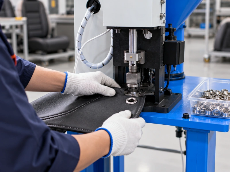
A guarded powered press with hand-loaded hardware or a semi-automatic feed can suit engineering trials, low-volume service parts, and programs with frequent hardware changes. The operator controls part presentation while the machine provides repeatable motion. This flexibility is useful only when the fixture still controls location and keeps hands away from the point of operation.
Stable Repeat Production
Automatic eyelet or washer feeding can reduce small-component handling when the same hardware and component configuration runs for a meaningful period. Prove the feeder with normal production lots, including permitted coating and dimensional variation. A feeder adjusted around selected samples may jam, double-feed, or misorient components from another approved lot.
Dedicated Positioning
A dedicated nest, index system, or automated part fixture can improve repeatability when the drawing and product geometry are stable. Confirm that the system detects missing or wrong components, prevents an incorrect orientation, and does not clamp on a sensitive appearance zone.
Compare output using accepted parts after loading, inspection, refills, and changeovers. For the broader architecture decision, refer to the manual, semi-automatic and automatic eyelet machine guide.
Define Acceptance From Customer Requirements
The acceptance plan should translate the released drawing, approved samples and qualification results into checks your production team can repeat. There is no universal eyelet height, flare diameter, setting force or pull value for automotive upholstery. Establish limits for the exact eyelet, washer, material stack, hole method, dies and machine setup.
- Hole center, edge distance, and orientation meet the drawing tolerance
- The flange and washer sit as specified without a prohibited gap, tilt, fold, or trapped layer
- The formed barrel matches the approved profile without unintended cracks, splits, burrs, or sharp projections
- The hardware does not spin or rock under the approved inspection method
- The visible face remains within the appearance standard for dents, rings, scuffs, gloss change, and coating damage
- Foam, backing, reinforcement, adhesive and substrate show no prohibited crushing, tearing, delamination or contamination
- Any functional load, cycle, corrosion or environmental test uses the customer-approved fixture, direction, condition and acceptance value
QC Machinery’s eyelet setting inspection standard provides a general measurement framework. Your automotive drawing and customer requirements take priority. If setting force is monitored, establish the permitted window from validated parts using the setting force window method rather than copying a value from another application.
Run a Representative Validation Trial
A valid trial covers the approved production range and the conditions most likely to expose a weak process. Send enough components for setup, adjustment, repeated operation, and inspection. Include the actual eyelets and washers from normal incoming lots. Record the machine, tools, fixture, settings, material codes, hardware lots, and drawing revision used for every result.
| Trial condition | Why it matters | What you should record |
| Thinnest and thickest local stacks | Challenges barrel-length range, clamp condition and finished height. | Stack build, thickness method, set profile, gaps, tilt, spin, and surface condition. |
| Softest and firmest constructions | Challenges compression, recovery, piercing and support. | Immediate result, delayed measurement where required, layer damage and dimensional result. |
| Most sensitive visible finish | Reveals die rings, scuffs, gloss change, oil and fixture marks. | Lighting and viewing condition, approved limit sample and defect location. |
| Normal hardware lot variation | Tests feeding and forming beyond selected development samples. | Supplier lot, component dimensions, feed interruptions, misorientation and accepted output. |
| Farthest reach and difficult geometry | Checks access, frame clearance, alignment, and part support. | Fixture datum, tool position, loading method, location results, and operator access. |
| Representative continuous run | Reveals debris, tool heating, feed drift, and gradual marking. | First, middle and final samples, stoppages, cleaning, rejects and accepted parts per hour. |
Condition materials only when the program requires it, and use the specified conditioning method. Do not invent a heat, humidity, or aging exposure for marketing purposes. If the customer requires capability data, measurement-system analysis, appearance approval, or a production part approval submission, agree on the sample quantity, gauges, study method, and records before the trial begins.
A successful sample does not automatically approve later changes. Revalidate as required when the eyelet, washer, finish, material construction, adhesive, hole method, die set, fixture, machine head, recipe, or supplier changes. The responsible customer or engineering authority must define the change-control threshold.
Build Traceability Into the Process
Automotive customers may require more process evidence than a general upholstery buyer. Capture only the records specified for the program, but design the station so those records can be produced. Useful controls may include a released setup sheet, machine and die identification, hardware and material lot traceability, first-off approval, inspection frequency, gauge status, reject reaction, and retained samples.
Keep the machine recipe tied to the part number and revision. Protect approved settings from unrecorded adjustment where the risk justifies it. After a tool change or feeder adjustment, run the required first-off checks before releasing production.
If your customer uses a control plan, process flow, PFMEA, or PPAP process, make sure the eyelet operation and its critical characteristics appear in the correct documents.
Customer-specific requirements differ and change over time. Obtain the current requirements from the customer or approved portal instead of relying on a general blog article. Do not describe the machine or process as IATF-compliant as a shortcut for product approval. A quality-system certificate, machine safety review, and part approval address different questions.
Include Safety and Maintenance in the Purchase Specification
The punch and dies create a point-of-operation hazard. Specify guarding, interlocks, two-hand control or another safeguarding method that matches the loading process and local regulations. The fixture should keep hands away from the closing tools and should not encourage an operator to hold a loose washer under the punch. Define safe methods for setup, jam clearing, cleaning and die changes.
Automotive trim can leave fibers, foam, adhesive, and coating residue around the tooling. Establish inspection and cleaning intervals during the trial. Check cutting edges, die alignment, feeder tracks, sensors and non-marking supports.
Stop the process when debris, tool wear, or fixture damage changes the hole, setting profile, or appearance. Maintenance frequency should come from the machine instructions and observed production conditions, not a copied cycle count.
Information to Send With Your Inquiry
- The released component drawing and bill of materials with eyelet location, datums, tolerances, and revision
- Written confirmation of the permitted application zone and any airbag, restraint, pedal or electrical restrictions
- Complete production-stage parts covering every approved layer construction and local overlap
- Eyelet and washer samples from normal lots with part numbers, dimensions, materials, finishes and supplier data
- The required hole-making method plus rules for debris and slug control
- Visible-surface criteria, hidden-side criteria and any required functional, environmental or corrosion test methods
- Part volume, batch size, change frequency and target accepted parts per shift
- Required fixture datums, error-proofing, safeguards, documentation, traceability, training and spare tooling
- The customer-specific approval process and the evidence required before production release
Common Mistakes to Avoid
Calling a Machine “Automotive Grade” Without Evidence
Automotive suitability must be demonstrated for a defined part, hardware system, process, and approval route. A general label cannot replace a sample report or customer release.
Testing a Loose Fabric Coupon
A coupon does not reproduce foam recovery, adhesive, reinforcement, seams, molded substrates, finished geometry, or access. Trial the part in the condition that reaches the press.
Approving Only the Visible Flange
The hidden roll can contain a sharp edge, trapped fold, crack, or gap. Inspect both sides and any nearby material or component that may contact the hardware in service.
Changing Hardware by Appearance
Two eyelets with a similar finish may differ in barrel length, wall behavior, coating, or feed geometry. Control the released part number and revalidate changes through the required process.
Using Force to Correct a Poor Stack or Die Match
Extra force cannot correct missing barrel length, unstable support, a dirty cut, or the wrong die profile. Separate the cause before changing the machine setting.
Automating an Unstable Product
Dedicated feeding and fixtures can become costly change points when the drawing, material, hardware, or supplier is still changing. Stabilize the approved inputs before committing to a rigid layout.
FAQ
Can a Standard Eyelet Machine Be Used for Automotive Upholstery?
Possibly, but only after the exact component, material stack, hardware, access, safeguarding, and customer requirements have been tested. A standard machine description does not confirm fit. Request a documented sample trial and configuration review.
Does an Eyelet Machine Need Automotive Certification?
The answer depends on the customer and your supply-chain role. Machine safety, the supplier quality system, process documentation, and approval of the finished component are separate matters. Ask the customer which certificates, records and submissions are required; do not treat one certificate as approval of the whole application.
Can You Set Eyelets in Seat Covers?
Only where the released design specifies or permits them. Confirm the material stack, eyelet function, and nearby safety features. Do not place or modify an eyelet near an airbag deployment seam, occupant-restraint feature, or structural seat function without written engineering and customer approval.
How Do You Prevent Marks on Visible Trim?
Use the approved die profile, polished contact surfaces, a clean non-marking support, and a fixture that does not drag across the face. Include the most sensitive color, grain, and gloss in the trial, then inspect it under the customer’s defined appearance condition.
Do Automotive Trim Eyelets Always Need Washers?
No. The fastener design, material stack, function, available space on the back side, and customer specification determine whether a washer is required. Do not add or remove one without validating the complete joint and updating the released documentation.
What Must Be Verified Before This Application Is Published?
Keep documented evidence that QC Machinery tested representative automotive-compatible parts and production hardware on the machine configuration being discussed. Record the customer or program requirements used for acceptance. Until those records exist, present this content as a specification guide and do not claim a proven automotive application.
Approve the Application Before Choosing the Machine
Begin with the released component, permitted eyelet location, and customer acceptance requirements. Define the complete stack and hardware, then validate the hole method, dies, fixture, surface protection, and controls on representative parts.
Choose feeding and positioning assistance after the approved process is stable. QC Machinery can review a configuration when you provide the parts, drawings, hardware, and validation plan. Automotive compatibility still requires documented sample results and responsible customer approval.