
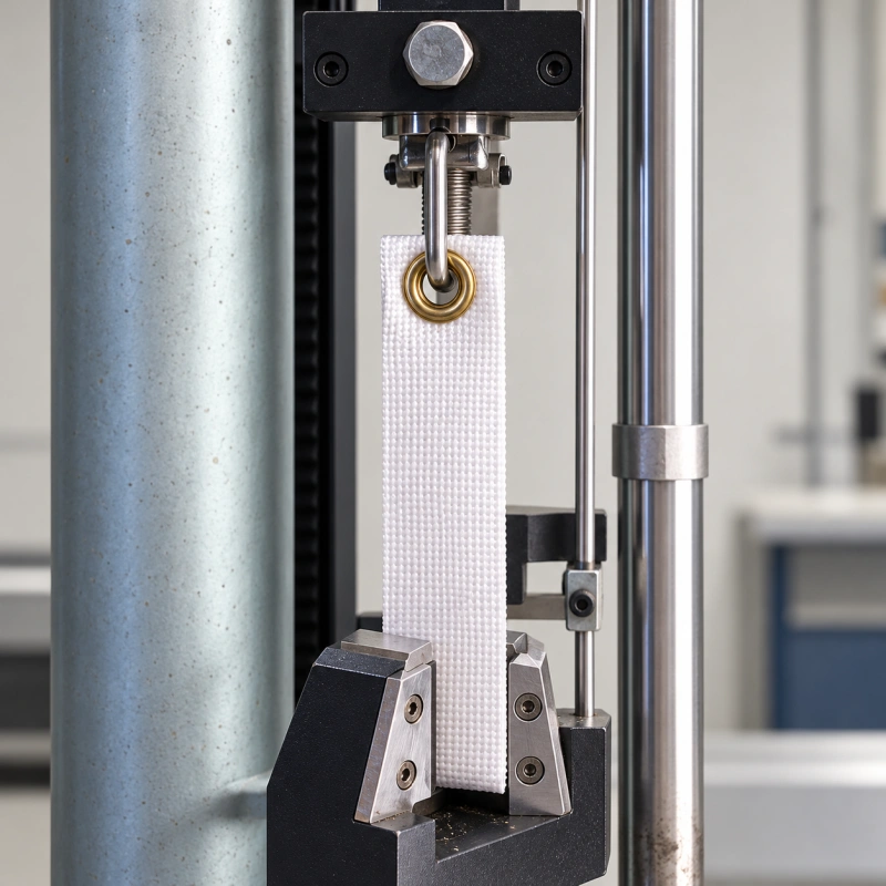
An eyelet may have a clean front flange and an even back roll, yet still release when the finished product is loaded. A visual check tells you whether the setting looks and measures as intended. An eyelet pull-out test asks a different question: how does this particular assembly behave under a defined load?
You need a method that another operator can repeat. That means fixing the material construction, the way you hold the sample, the direction and rate of loading, and the point you call failure. Otherwise, two force readings can look comparable while measuring different things.
The eyelet setting inspection standard covers visual and dimensional limits; this guide covers the mechanical test that follows when retention matters.
Quick Answer: How Do You Test Eyelet Pull-Out Strength?
1. Write down the purpose: development comparison, first-off approval, routine QC, or failure investigation.
2. Define the load path, failure point, test condition, and acceptance rule before seeing any results.
3. Make separate specimens with the actual material stack, hole, eyelet, washer, edge distance, and production setting process.
4. Identify every specimen and inspect it before loading. Keep visibly defective settings in their own category.
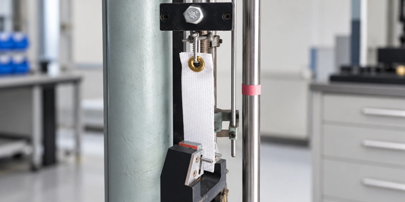
5. Clamp the material and engage the eyelet with a fixture that does not cut, slip, bend, or support the tested area artificially.
6. Align the fixture and apply force in the specified direction at a documented, consistent rate.
7. Record the peak force and the first relevant damage or release event according to your defined observation method.
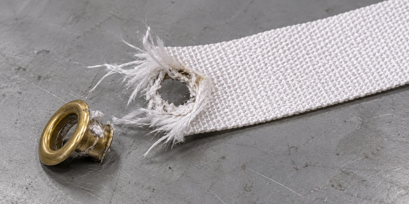
8. Photograph and classify the failed assembly, including any fixture failure.
9. Compare the individual results, not just the average, with the approved product-specific criterion and the previous production baseline.
10. If a valid result fails, follow the approved containment rule. If results show a warning trend, investigate and increase checks as the control plan requires.
There is no universal eyelet pull-out force that makes every garment, cover, strap, or panel acceptable. Your product requirement and validated method must supply the limit.
What Does a Pull-Out Test Measure?
In a destructive test, the peak reading is the highest force observed under your specified setup. It is a result for the whole assembly: eyelet, washer if used, material, reinforcement, hole, setting, and load geometry. It is not an isolated rating for the metal eyelet.
An eyelet can leave the hole intact, the surrounding fabric can tear first, or a backing patch can separate. Those outcomes may produce similar peaks but call for different decisions. Record the first relevant event as well as the final break if your product specification distinguishes them.
An early tear followed by a higher peak does not necessarily count as a pass. Define whether failure means first visible damage, first force drop, loss of eyelet retention, or complete separation.
A single pull to failure does not establish performance under repeated loading or weathering. Qualify those separately if the product requires them.
Define the Test Before Preparing Samples
Start with the product drawing or customer requirement. Which component carries the load in use: a cord through the hole, a hook, a strap, or the sheet material itself? Does the load act out of the material plane or toward a nearby edge? Are you measuring ultimate failure force, survival of a proof load, or a comparative difference between two constructions? These are separate questions.
Write one short method sheet for each distinct configuration. Specify the specimen construction and size, conditioning if required, fixture and contact shape, free span and clamp location, pull direction, loading rate, failure definition, number and timing of samples, units, and decision rule.
Record the test equipment and its verification status. A customer-specified procedure takes precedence; if none exists, qualify an internal procedure and identify it as an internal method rather than claiming compliance with a standard.
If the grip slips or causes damage outside the intended failure area, treat the run as invalid, correct the setup, and retest a new specimen. If a break at or near the grip follows the product’s intended load path, record it as an assembly failure. Do not dismiss an actual product failure as a fixture error.
Prepare Representative Production Specimens
Use the construction that will ship. If a finished corner contains coated fabric, a folded hem, stitching, a reinforcement patch, and lining, test that complete arrangement. A convenient flat, single-layer offcut may be useful for early screening, but it cannot qualify the finished corner. Make the hole with the production punch or approved hole-making process.
Set the production eyelet and washer, if specified, using the approved machine and tooling.
Keep material and component lots, thickness and layer order, reinforcement, hole process, edge distance, orientation, and setting position traceable. Record relevant conditioning; never mix different constructions or conditions in an unlabeled result set.
Make independent specimens across the relevant run. Several pulls from one setup strip say little about a later roll or component lot. Identify each piece before testing.
Qualify mechanically distinct positions separately. A coupon can replace a finished part only after you show that its construction, geometry, and failure behavior represent the real assembly.
Choose a Fixture That Does Not Create the Failure
The material grip must hold the specimen without initiating a tear. The eyelet contact should transfer force as the method specifies without prying the metal in an unintended direction. Keep the loading line aligned; avoid a fixture that leans on the washer or braces the material around the flange when the product would not receive that support.
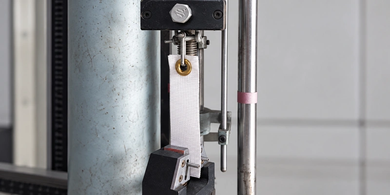
Watch early trial pulls. Jaw slip, jaw cuts, or premature eyelet crushing require a fixture correction. Protected grips may help delicate textiles, but their padding, pressure, and spacing must remain consistent.
Check the force trace and failed piece together. Flag grip slip or grip-induced damage outside the intended failure area as an invalid run, then correct the fixture and retest a new specimen. Record a break that represents the product’s intended load path as an assembly failure. Qualify the fixture before routine QC.
Fix the Pull Direction and Load Path
“Pull-out” can describe several tests. In a normal-to-plane pull, force acts through or against the eyelet away from the material surface. An in-plane pull acts along the material, often loading the bridge from the eyelet to an edge.
An angled cord can combine these actions and add local bending. They may produce different peak forces and failure modes. Results from one direction are not interchangeable with results from another.
Choose a direction that answers the product question. A corset lace pulls toward an edge; a straight normal pull may miss that failure. If use involves more than one critical direction, define separate tests.
Mark the face, pull direction, and orientation on the method sheet. Keep the initial angle and specimen tension consistent. Even a good fixture becomes a different test if an operator rotates the material to make clamping easier.
Run the Test the Same Way Each Time
1. Confirm the approved method revision, instrument range, fixture, and required equipment checks. Use equipment with suitable resolution for the expected force range.
2. Check the sample ID and inspect both faces. Record visible damage or a wrong component before the destructive test; follow your quality plan for how such a sample is classified.
3. Mount the material at the specified grip position and engage the eyelet without pre-damaging it. Align the force path and zero the measurement as the equipment procedure requires.
4. Apply force smoothly at the rate in your customer specification or validated internal method. Do not alternate between a rapid jerk and a slow pull. If a proof load or hold period is required, define it separately from a pull-to-failure test.
5. Observe when the first defined damage occurs. Continue to the endpoint required by the method, while respecting the tester’s guards and operating instructions.
6. Save the peak force in a stated unit and classify the failure mode. Record force at first damage only when the event can be identified reliably from the force trace, video, or a defined observation method. Photograph both sides where useful and note any deviation from the method.
Do not invent a loading speed because it seems common in another fastener test. Speed, grip separation, and specimen dimensions should come from the applicable specification or your own validated method. Recheck the setup whenever a different technician or test stand produces a shift in the results.
Record the Conditions Behind the Force Reading
An isolated number cannot tell you whether the product changed or the test changed. The following compact record keeps the result traceable without asking the technician to rewrite a full engineering report for every sample.
| Record Field | What to Capture |
| Identity | Date and time; product/job; specimen ID; run, shift, and sampling point |
| Assembly | Material and lot; finished stack or thickness range; reinforcement; eyelet and washer IDs/lots; hole and edge position |
| Setting | Machine/head; die set; approved setup or recipe revision; operator when needed for traceability |
| Test | Method revision; fixture; direction; rate or program; tester ID and verification status; conditioning when applicable |
| Result | Peak force and unit; first-damage force if reliably measurable; failure mode; pass/fail; photo or observation; disposition |
These fields help distinguish material, component, machine, and test variation. Link the result to the approved setup; see documenting a working eyelet setup for the wider production record.
Classify the Failure Mode, Including Test Errors
Use short, consistent codes if you plan to trend the data. A code should describe what happened; it should not pretend to prove the cause. Retain the specimen when the failure is unusual.
| Observed Mode | What You See | Next Check |
| Eyelet pulls through the material | Hardware releases with limited surrounding tear | Compare the original hole, formed back, and washer capture with approved samples |
| Material tears toward an edge | A split reaches a free edge while hardware may remain formed | Check edge distance, construction, and in-plane load direction |
| Washer releases or passes through | Back component separates or pulls through before the front | Check component match, back formation, and actual load path |
| Metal deforms or separates | Flange or barrel changes shape before retention is lost | Check eyelet specification, contact geometry, and setting damage |
| Hole grows or layers separate | Progressive opening, coating split, or reinforcement delamination | Check material construction, bonding or stitching, and first-damage criterion |
| Grip slips or damages sample | Movement in jaws or damage caused by the grip outside the intended failure area | Flag an invalid run if grip-induced; correct the fixture and retest. Record product-representative failures |
One specimen may show more than one event. Record their order: for instance, coating delamination before a final edge tear. If you need to diagnose and correct a pull-through problem, see the dedicated pull-through failure guide. This table serves the test record, not a complete repair procedure.
Choose Sampling for the Process You Run
There is no universal sample count. Customer requirements, application risk, variation, volume, and destructive-test cost all affect how many and when. Define both in the control plan.
During initial validation, test independent pieces from the relevant material thicknesses, positions, and production conditions. Use enough results to see whether low readings or a specific failure mode cluster in one construction.
At startup, perform first-off checks after setup approval. During routine production, sample at defined intervals or quantities, including the machine heads and material positions that matter. Increase checks after an abnormal trend, lot change, maintenance, or restart. Investigation testing has a different purpose: compare suspect output with controlled, traceable reference samples.
Keep routine visual checks and destructive pull tests in the same quality plan, but give them their own frequency. If a pull test fails, follow the containment rule agreed before production: identify output since the last acceptable check, hold the affected material, determine cause, then repeat first-off approval before release.
Do not assume that passing samples on either side of a failure prove every intervening part is good.
Set an Application-Specific Acceptance Limit
Start with the customer’s drawing or the product engineering requirement. Specify the required service function, relevant load direction, and whether an eyelet must survive a defined proof load or meet a minimum destructive strength.
Consider foreseeable material variability, the effect of environmental exposure where relevant, and the consequence of failure. Development trials on representative production assemblies can then establish what the process is capable of delivering.
Keep the requirements and process indicators separate. The service requirement describes what the product must withstand. The minimum acceptance limit determines product disposition under the specified test. The process target describes normal production performance, with room for variation.
A separate warning trigger prompts a process check before results reach the acceptance limit. Do not set that limit simply by averaging a few good-looking samples, and do not publish a machine setting as an eyelet pull-out rating.
Agree whether the decision applies to each valid specimen or to a defined sampling statistic, and how an unacceptable failure mode affects the verdict. A high peak reading may still fail if a seam starts tearing below the allowed load. If another component breaks first while the eyelet remains attached, the test has not established the eyelet assembly’s ultimate pull-out force.
Record what failed and follow the method’s rule for that result.
Once the criterion is approved, use the same test method to check that the production setting delivers it without crushing the material. The correct eyelet setting-force window explains how to qualify the machine process; material thickness vs. press pressure covers the related setup problem. Neither page supplies a universal retention limit for your product.
Respond to a Low or Unstable Result
First confirm the test itself: sample identity, load direction, fixture slip, instrument status, conditioning, and method revision. A valid low result deserves containment under your quality procedure, even if neighboring parts appear normal. Compare the failed piece with accepted pieces from the same job and retain both.
Next, look for what changed: material lot or thickness, folds or reinforcement, hole-making, edge position, eyelet or washer lot, machine head, tooling, and setup. Use the recorded failure mode to prioritize checks, then change one controllable variable at a time where practical.
Re-test enough representative pieces to show that the proposed correction works under the original method. Do not raise the press setting merely because one force reading fell; added forming can damage the material.
Watch for a downward series of readings that still pass. A changing failure mode or growing spread can signal drift before the first rejection. The action threshold and response belong in the same approved control plan as the release limit.
Revalidate After a Meaningful Change
Previous results belong to a defined combination and procedure. Review validation when the material supplier or construction changes; when reinforcement, hole process, edge geometry, eyelet, washer, die, machine head, or setting recipe changes; or when the fixture or test program changes. A customer specification revision, repeated field failure, or unexplained trend also calls for review.
Assess the change and approve a proportionate plan. Compare old and new fixtures on controlled specimens before combining their data. Establish a fresh baseline for a changed assembly.
Production Pull-Out Test Checklist
Before: Confirm the method revision and criterion. Identify the actual construction and production setting. Check the eyelet, washer, hole, edge position, conditioning, fixture, instrument, and pull direction. Label specimens.
During: Keep the clamp position and alignment consistent. Apply the specified load program. Note first relevant damage, peak force, and any slip or fixture damage. Keep invalid tests separate from true assembly failures.
After: Record the individual results and failure modes. Compare with the approved limit and recent baseline. Hold affected output when the reaction rule is triggered. Retain useful failed and reference samples, investigate, and reapprove the run before release.
For sample-trial advice, send QC Machinery your finished construction, eyelet and washer specifications, hole and edge geometry, load direction, performance requirements, and representative pieces. We can discuss the test and the machine and tooling information needed before production approval.